ACI Lab 2024
Configure Interface Policy Group
Configure Virtual-Port Channel [VPC]
Access Provisioning Flow Chart
Overview Tenant, VRFs, DBs & SVIs
Create Tenant, VRFs, BDs & SVIs
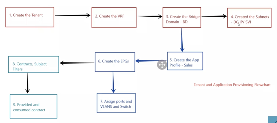
Application Provisioning Overview
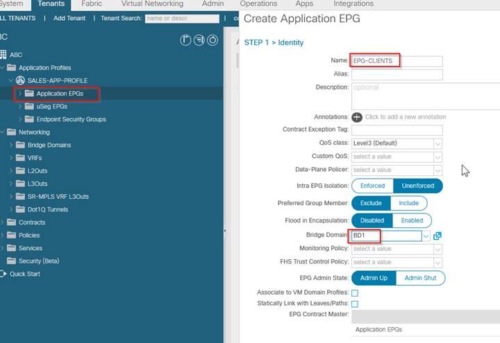
Creating the Application Profile, EPGs and Assign the Ports to
Creating and Provisioning the Contracts, Subjects and Filters
Configure L3-OUT, EPGs & Contracts
Transit Routing through the ACI Fabric
External Firewall Integration Overview
Configuring Firewall Integration
Firewall Services for External Firewall
Single-Pod Single Cluster vs Multi-pod Single Cluster
Multi-pod Single Cluster - Stretched Fabric
Multi-Pod Single Cluster - Using IPN
--------------------------------------------------------------------------------------------------------------------------------------------------------------------------------------
--------------------------------------------------------------------------------------------------------------------------------------------------------------------------------------
Preparation
ACI SIMULATOR
Note Registration
--------------------------------------------------------------------------------------------------------------------------------------------------------------------------------------
--------------------------------------------------------------------------------------------------------------------------------------------------------------------------------------
Configure Interface Policies
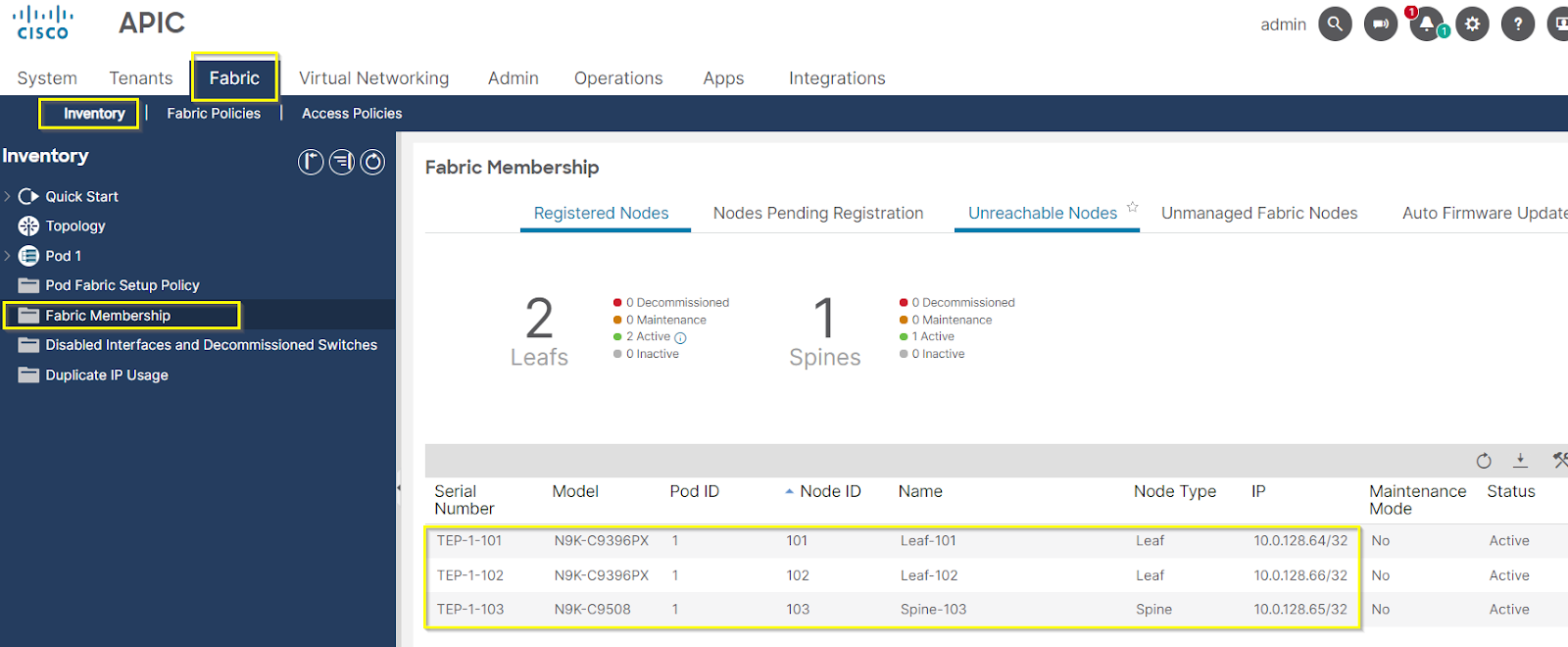
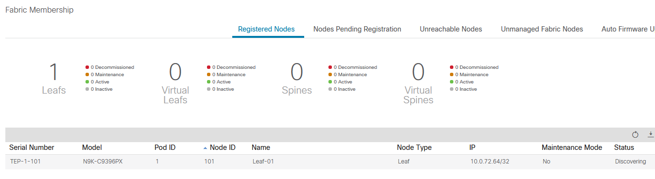
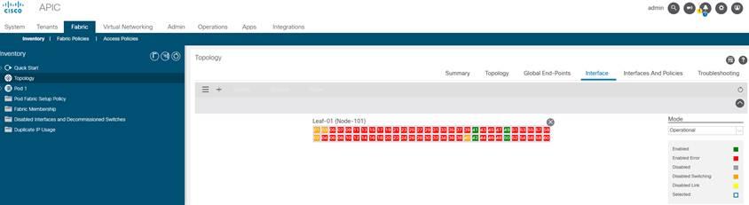
Fabric Discovery
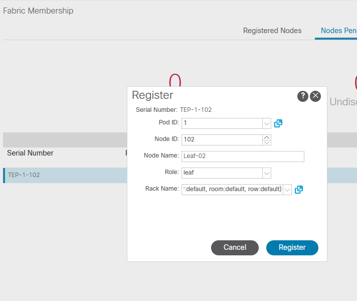
Register leaf-01
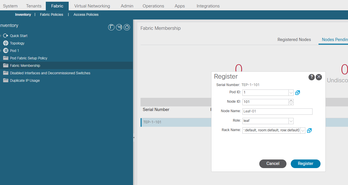
Confirm node registration
Once leaf discovered, spine will be discovered
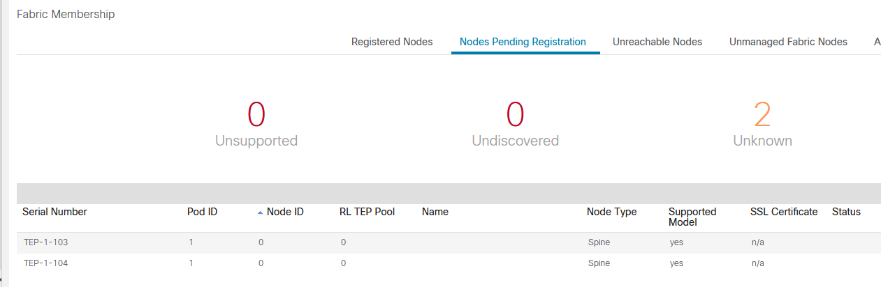
Register spines
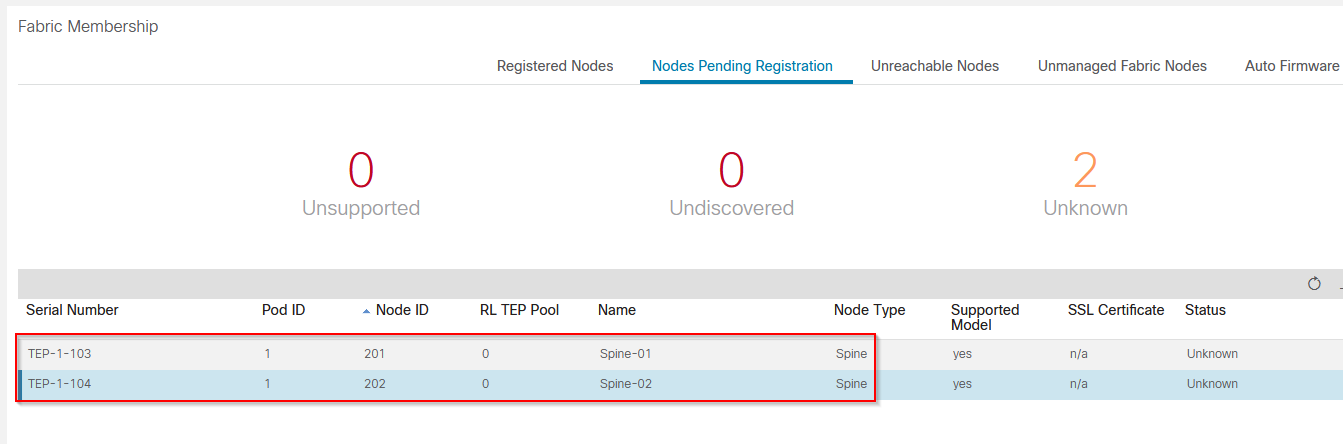
Once Spines registered, second Leaf will be discovered
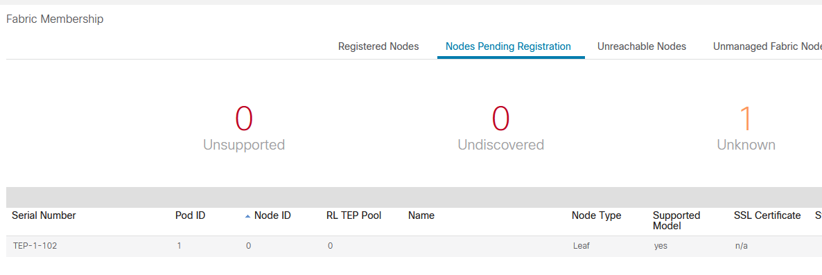
Register second leaf
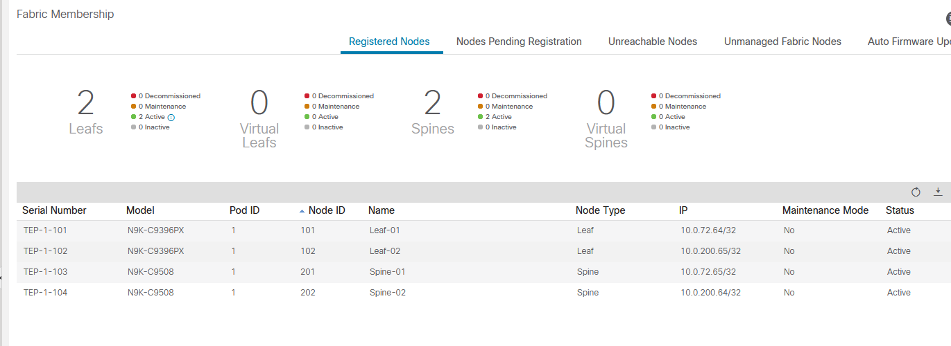
Confirm leafs and spines registered
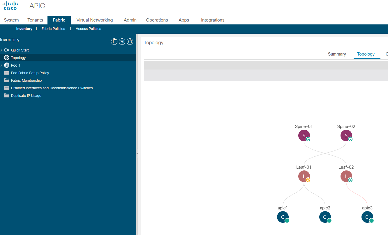
Review topology
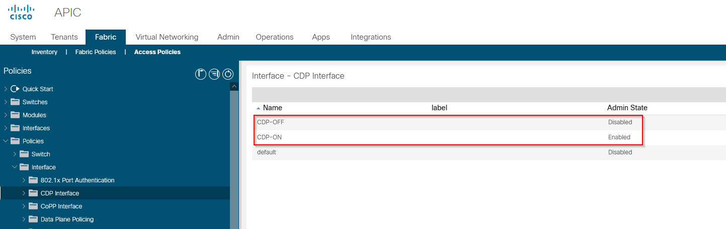
Create CDP Interface Policy
Create LLDP Interface Policy

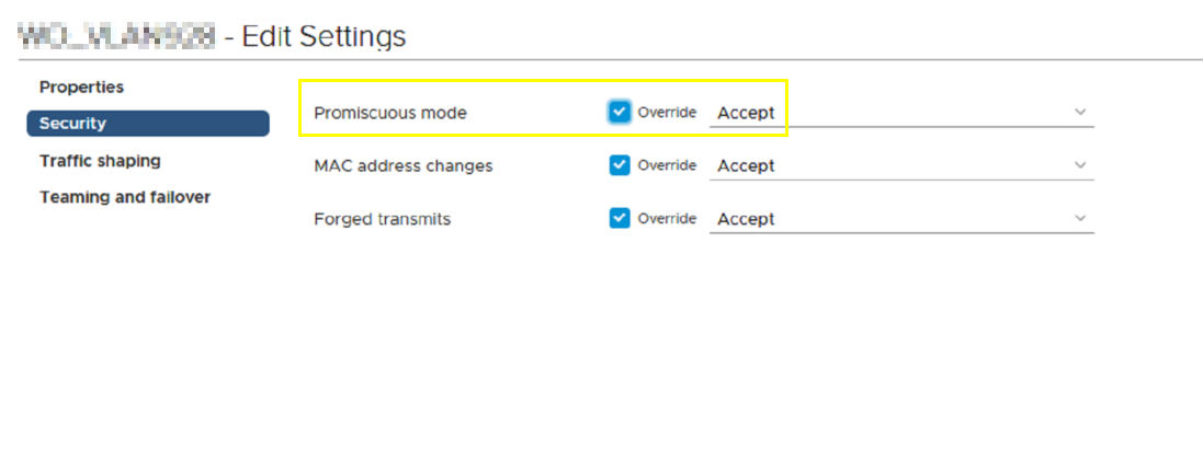
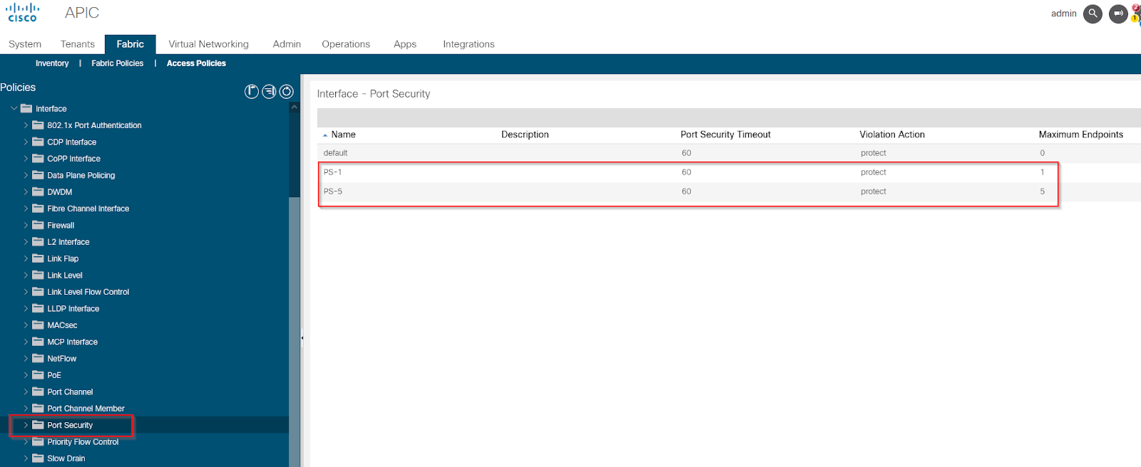
Create Port security policy
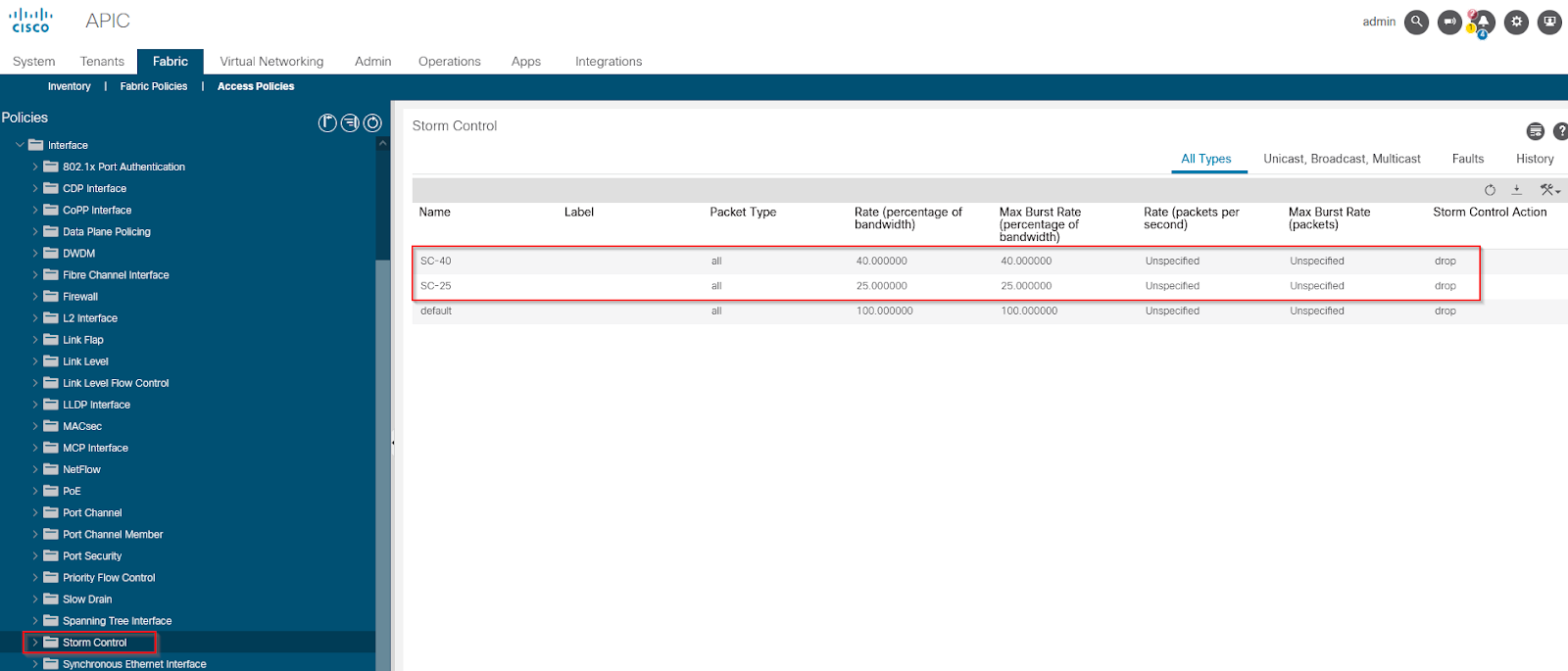
Strom control policy
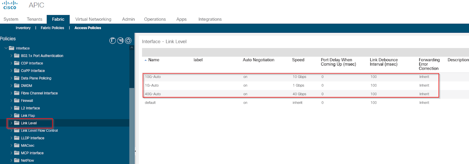
Link level policy
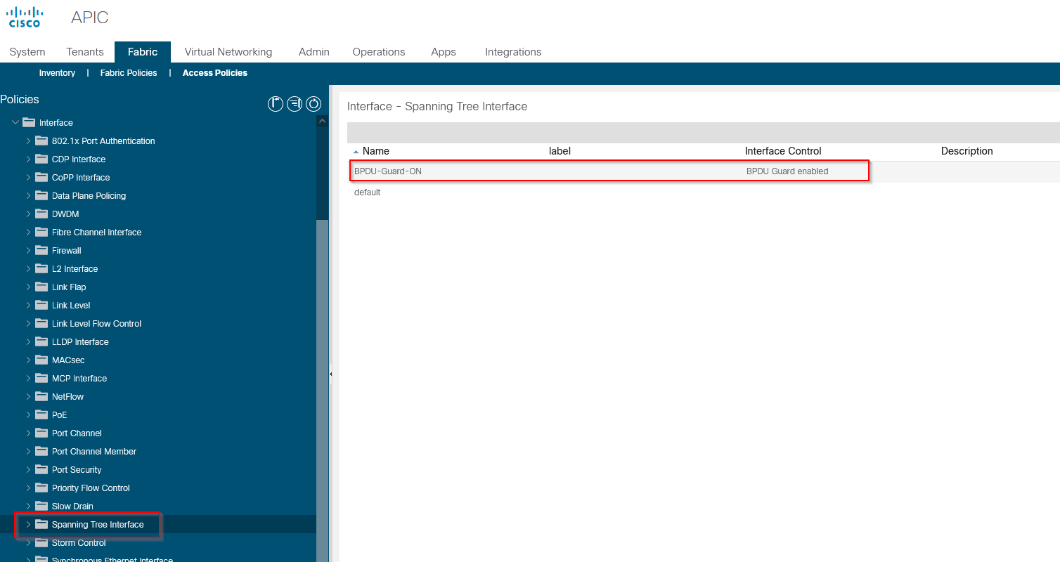
BPDU Guard Policy
--------------------------------------------------------------------------------------------------------------------------------------------------------------------------------------
--------------------------------------------------------------------------------------------------------------------------------------------------------------------------------------
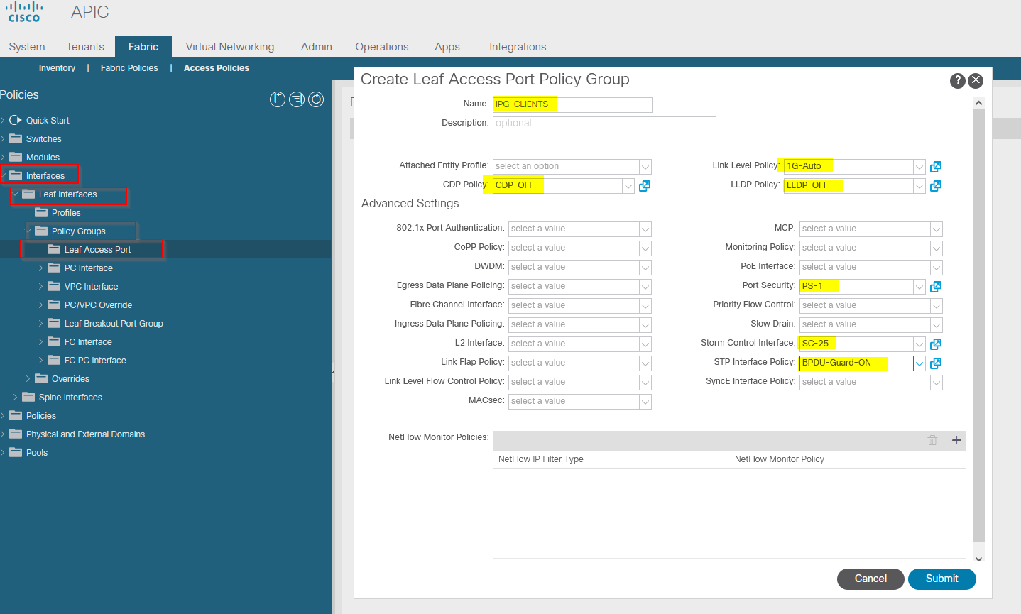
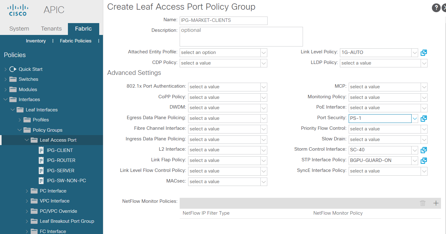
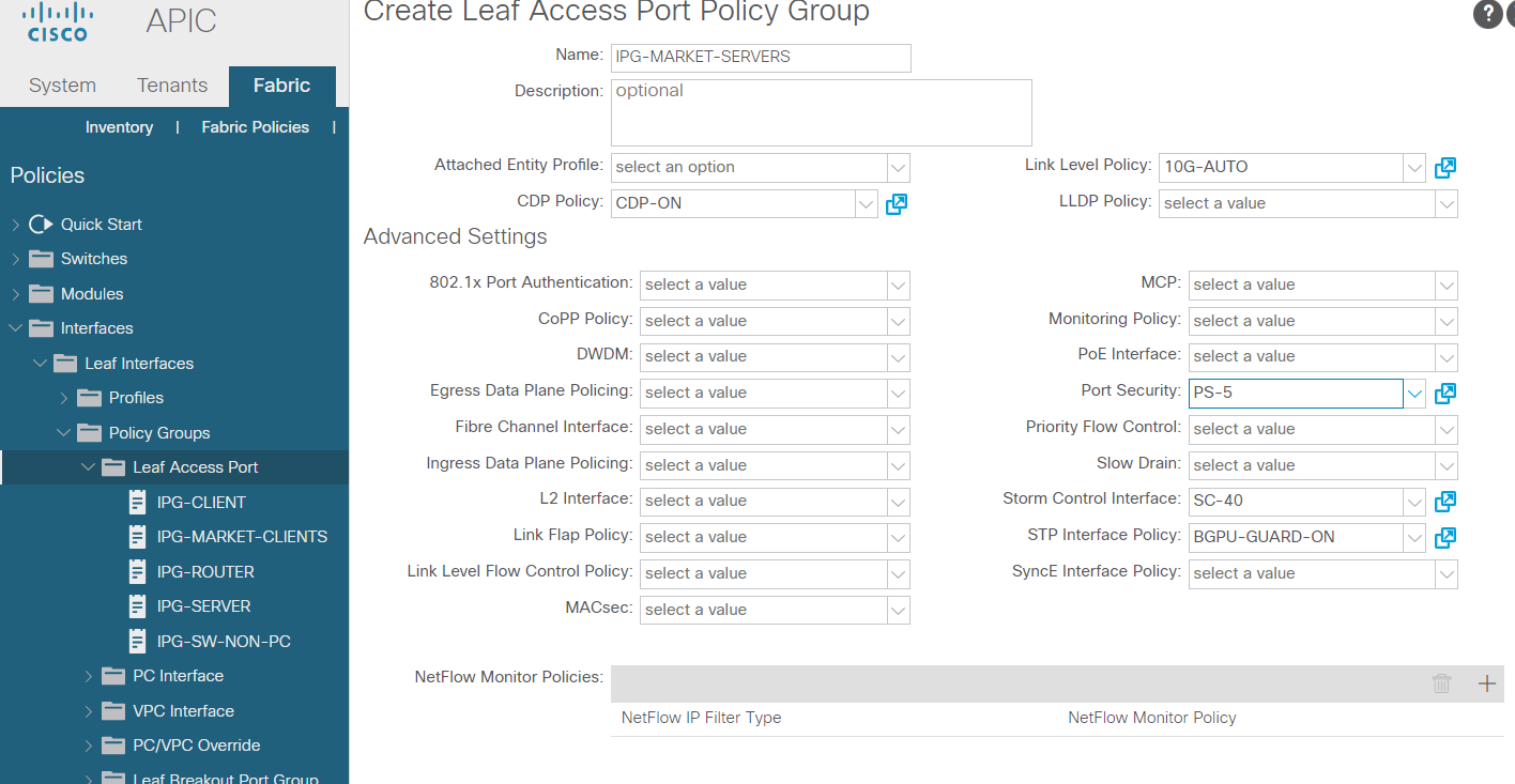
Configure Interface Policy Group
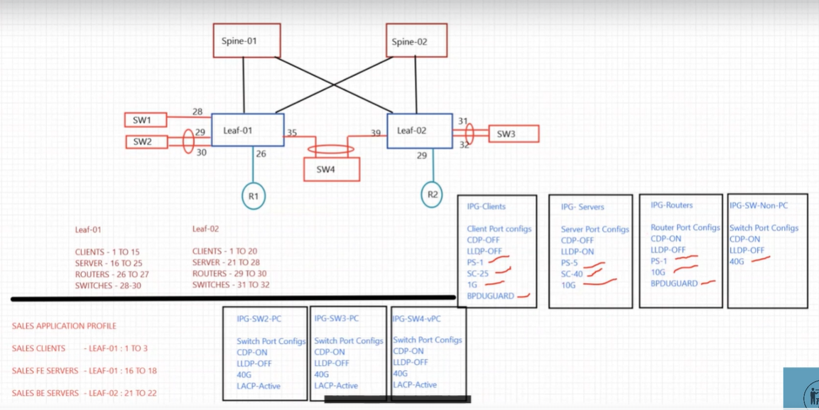
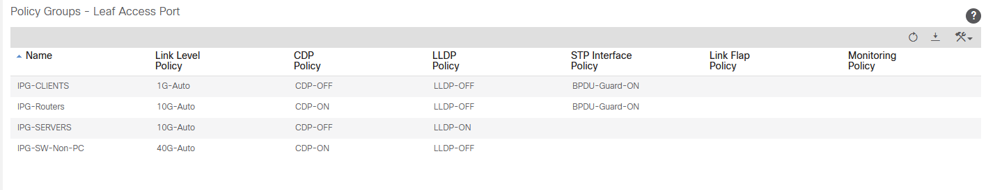
Create IPG-CLIENT, IPG-SERVERS, IPG-ROUTERS, IPG-SW-NON-PC and call the individual interface polices inside each IPG. We allocate the IPGs to a port of the Leaf switch not the individual interface polices.
Create “IPG-CLIENT”
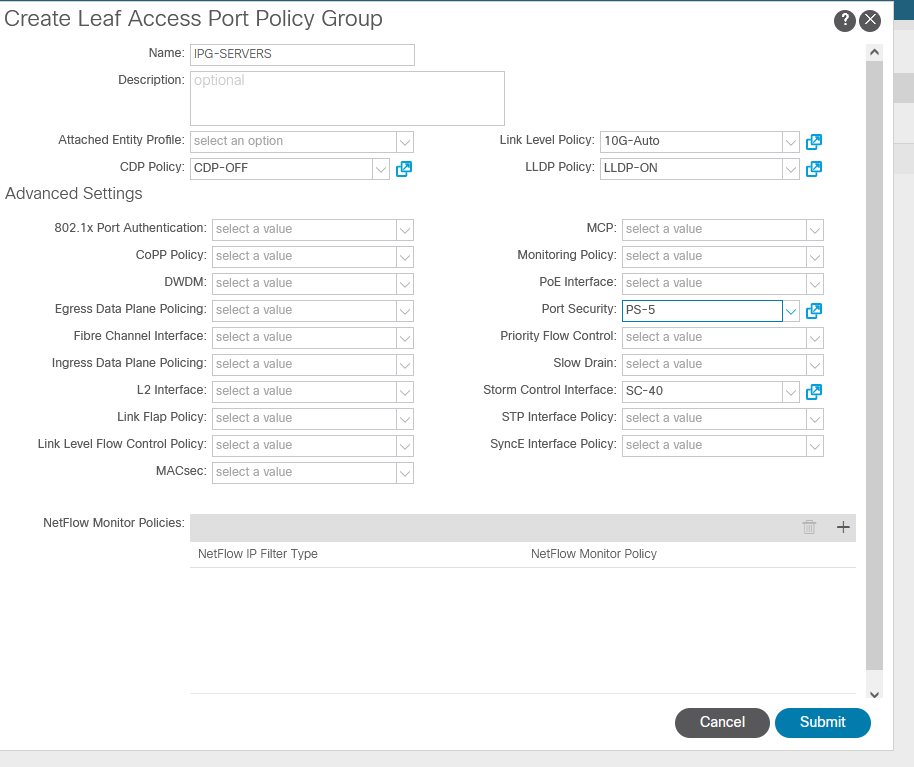
Create “IPG-SERVER”
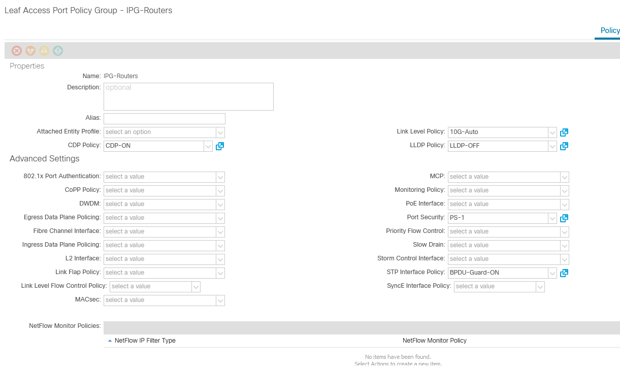
Create “IPG-Routers”
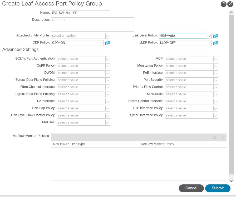
Create “IPG-SW-Non-PC”
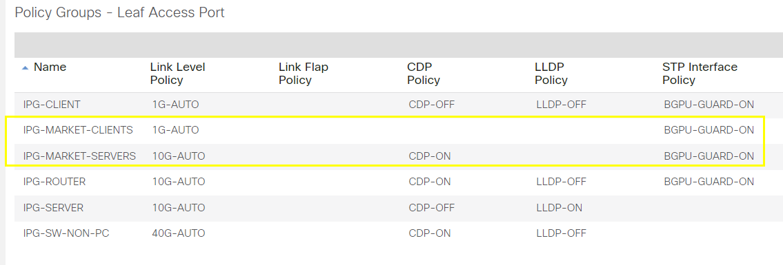
Review newly created IPGs
--------------------------------------------------------------------------------------------------------------------------------------------------------------------------------------
--------------------------------------------------------------------------------------------------------------------------------------------------------------------------------------
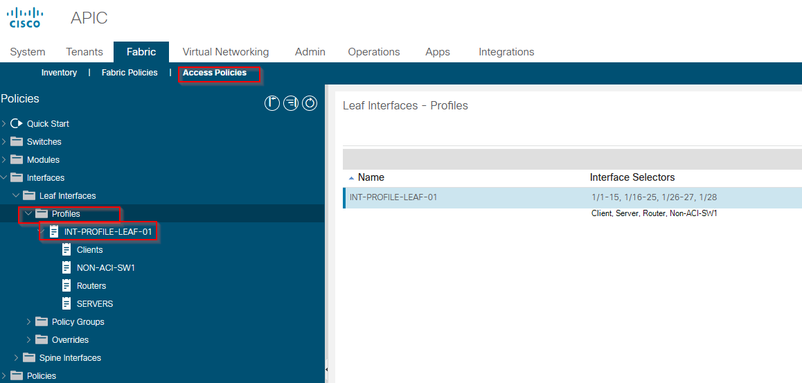
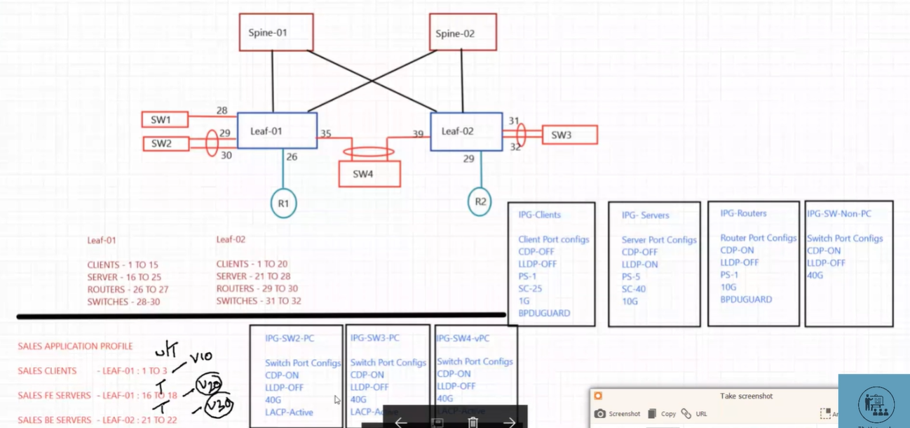
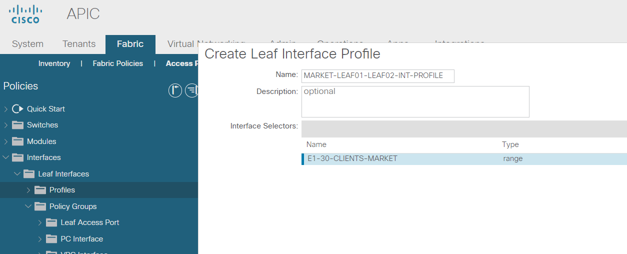
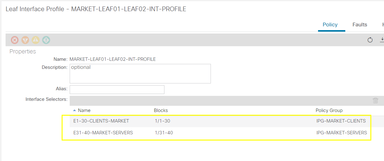
Configure Interface Profiles
It means to allocate the IPGs we created and attach them to Leaf-01 and Leaf-02 by defining the Breakdown of the Interfaces.
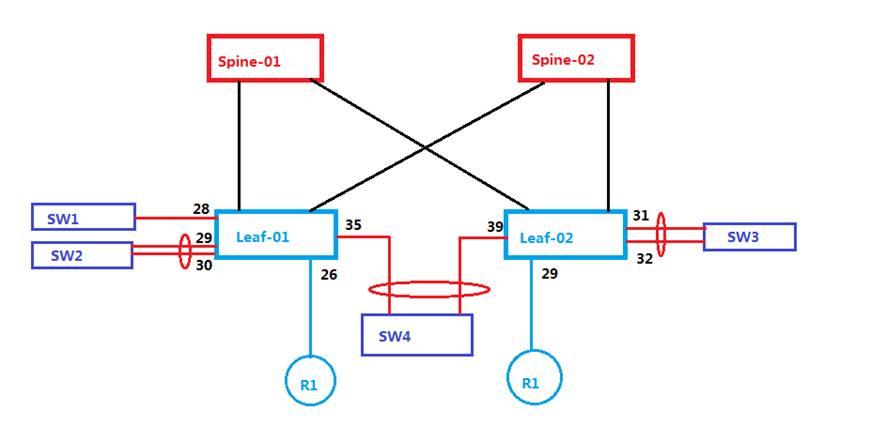
So as per the diagram we would need to assign the following:
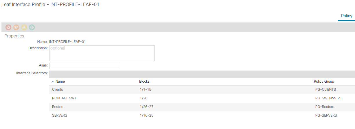
Leaf-01:
Client p1-15
Server p16-25
Routers p26-27
Switches p28-30
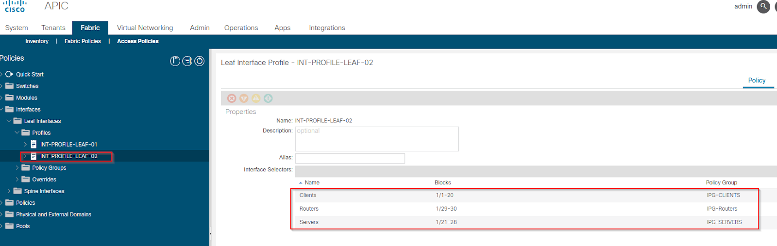
Leaf-02:
Client p1-20
Server p21-28
Routers p29-30
Switches p31-32
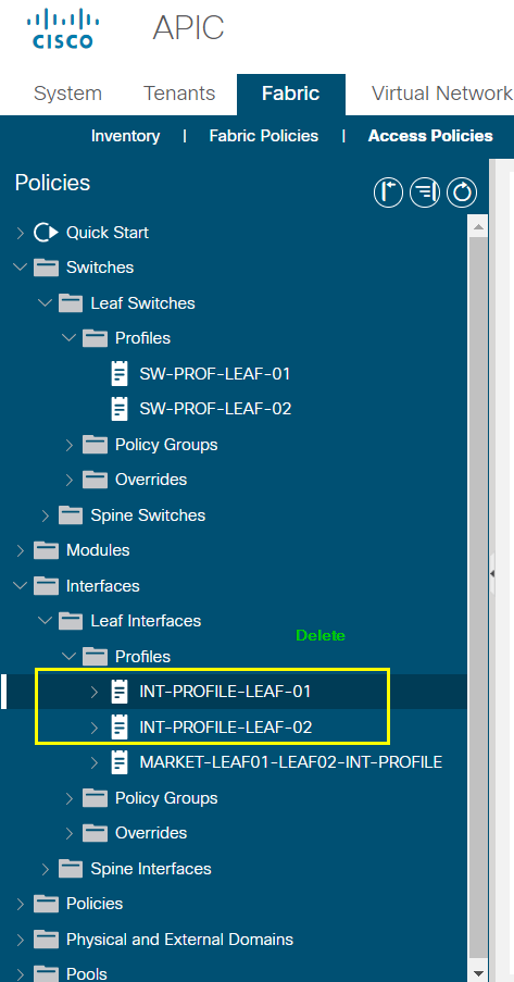
Create interface profile “INT-PROFILE-LEAF-01”
Create interface profile “INT-PROFILE-LEAF-02”
--------------------------------------------------------------------------------------------------------------------------------------------------------------------------------------
--------------------------------------------------------------------------------------------------------------------------------------------------------------------------------------
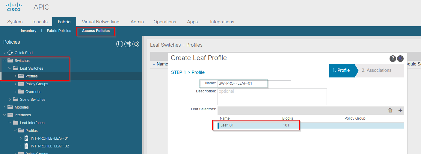
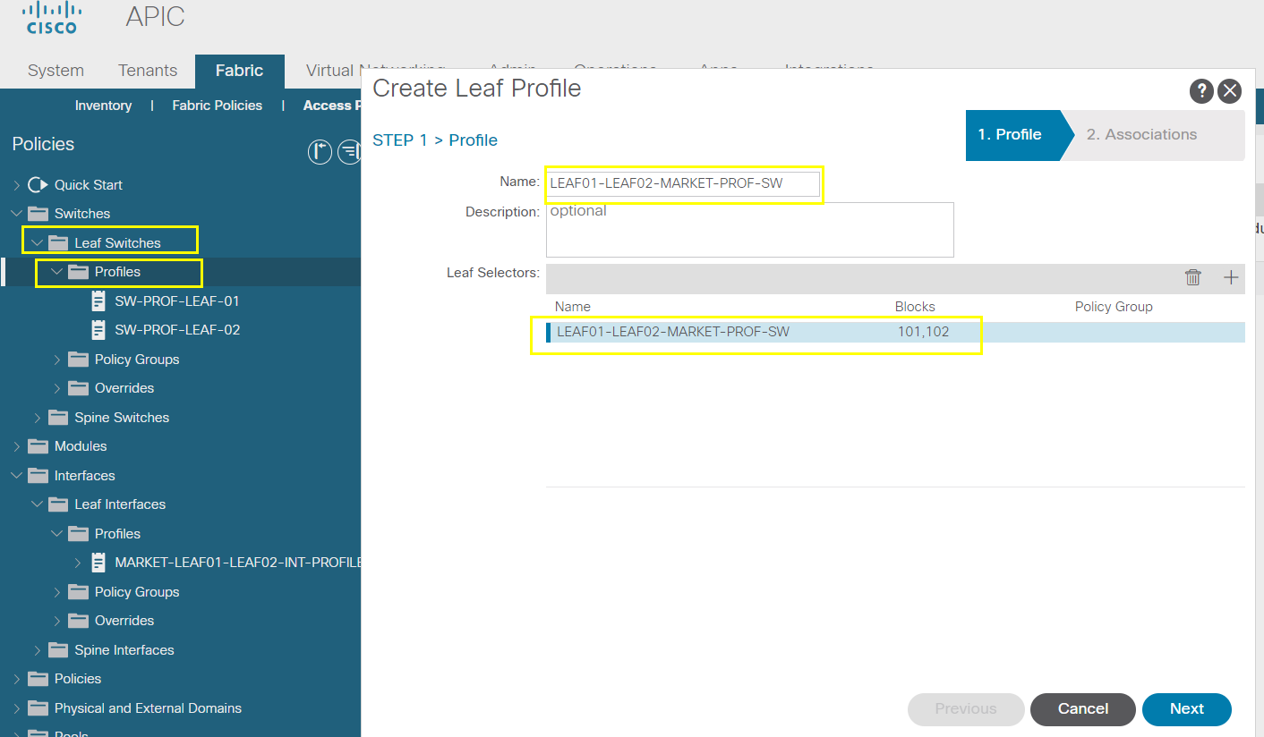
Configure Switch Profile
So far with the previous steps we made the cut out ready but didn’t apply to the actual Leaf switches yet.
By configuring switch profile we are going to apply the above steps to the respective leaf switches.
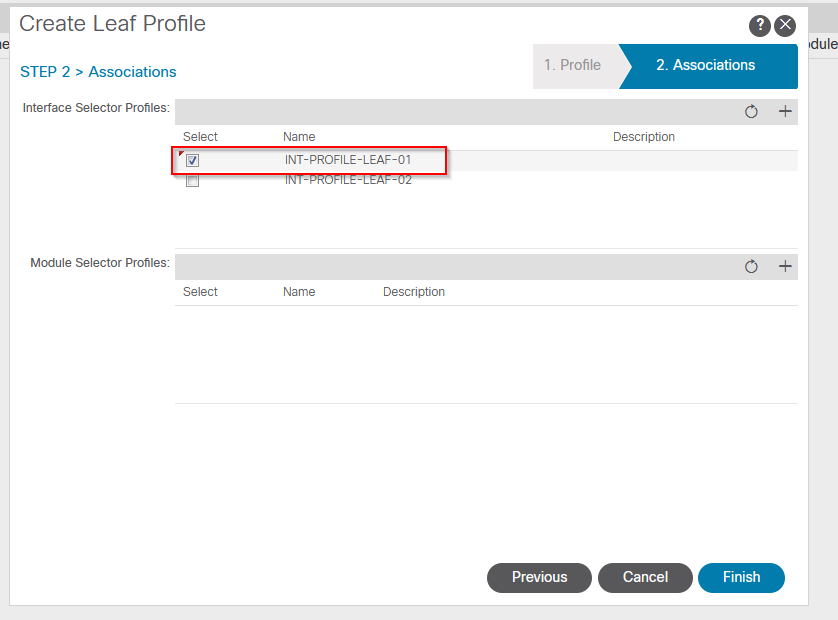
Create “SW-PROF-LEAF-01”
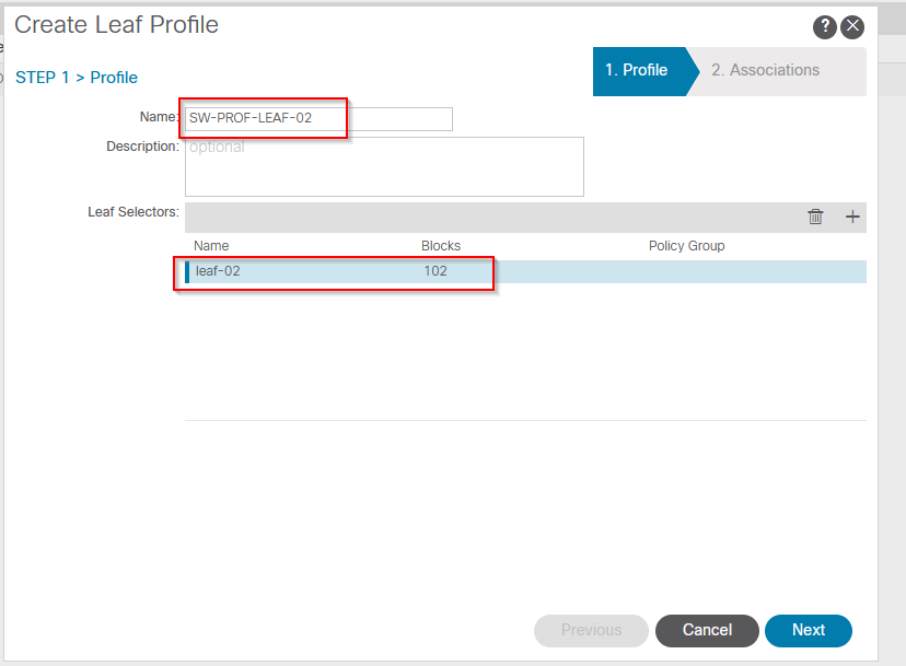
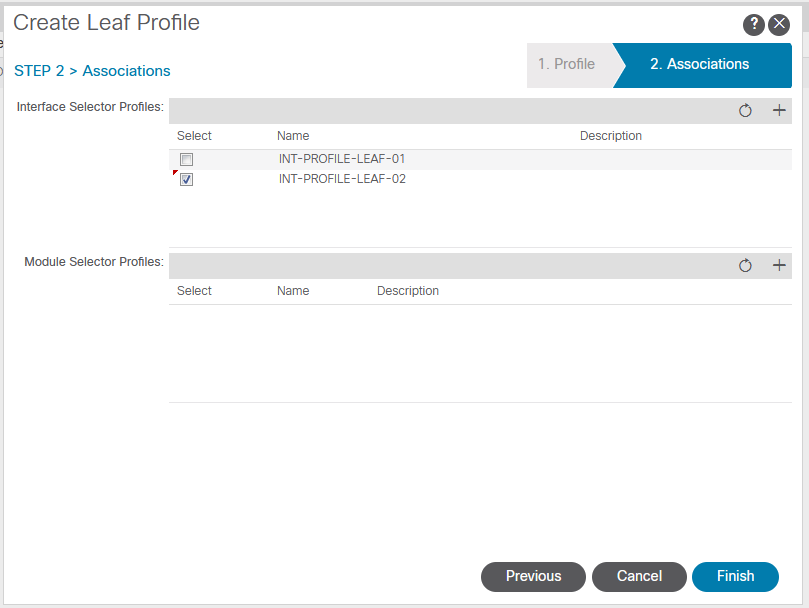
Create “SW-PROF-LEAF-02”
--------------------------------------------------------------------------------------------------------------------------------------------------------------------------------------
--------------------------------------------------------------------------------------------------------------------------------------------------------------------------------------
Configure Port-Channel
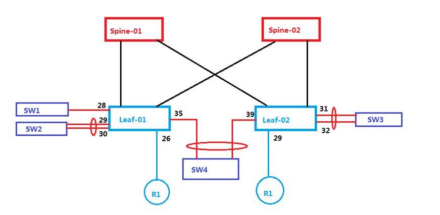
Based on the topology diag
We are going to learn how to connect NON-ACI switch using port-channel (PC) and VPCs
Check port status
Port-channel Modes
On
Static
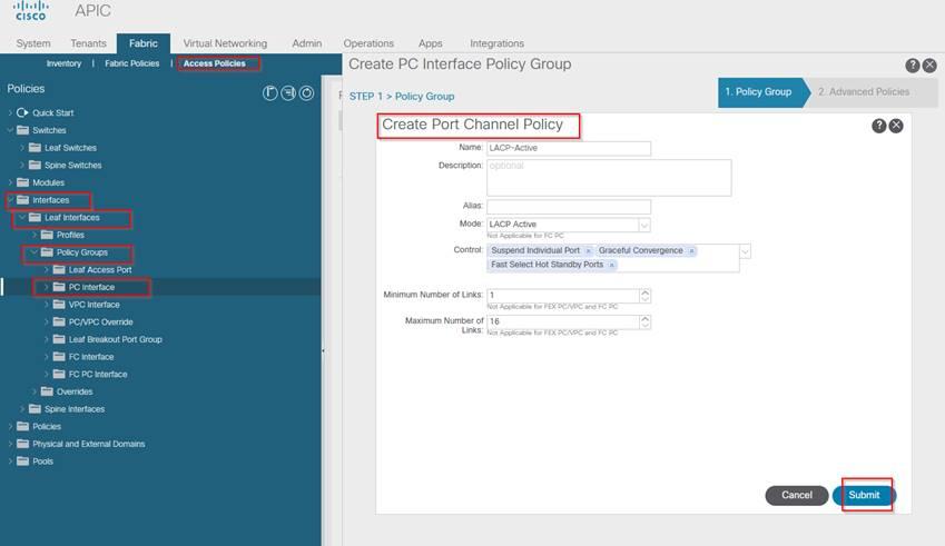
LACP
Active
Passive
Based on the channel group ID – 10, the physical interface belongs to a PC group
In ACI switches the same stitching mechanism is done using IPGs. So we need to create separate IPGs to connect the NON-ACI switches in point to point PC manor.
But those separate IPGs can have same interface policies
Let’s perform the PC lab as per the diagram for Leaf-01 and Leaf-02
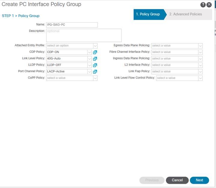
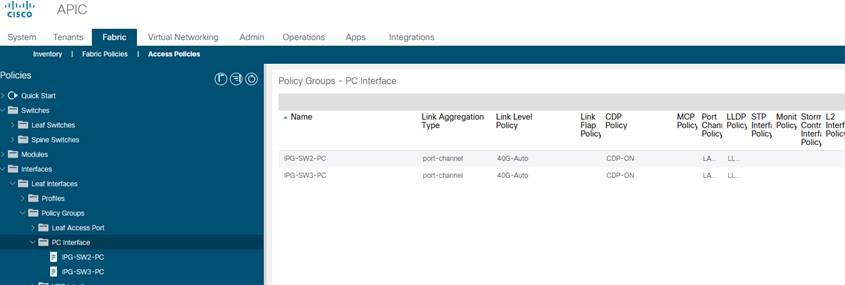
Create IPG “IPG-SW2-PC”
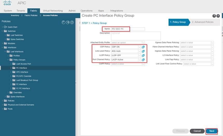
Create IPG “IPG-SW3-PC”
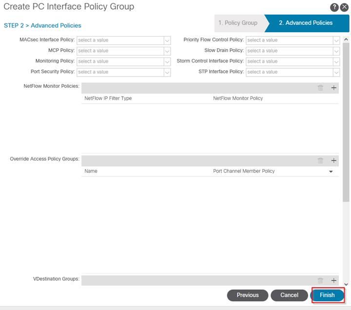
Next and Finish
Assign IPG to Interface Profile
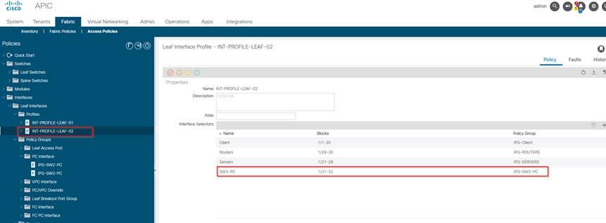
Fabric > Expand Interfaces > Expand Leaf Interfaces > Expand Policy Group > RC PC Interface and Select ‘Create PC Interface Policy Group’
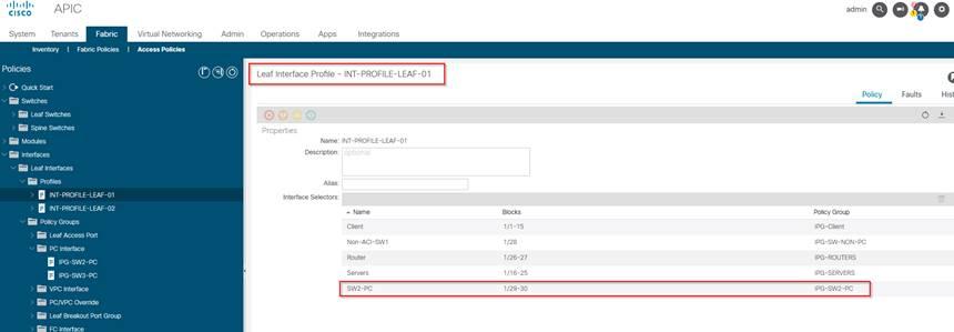
To Apply the IPG-PC we made to the Interface Profile of Leaf switches that we already created
Fabric > Access Policies > Interfaces > Leaf Interfaces > Profile > INT-PROFILE-LEAF-01
--------------------------------------------------------------------------------------------------------------------------------------------------------------------------------------
--------------------------------------------------------------------------------------------------------------------------------------------------------------------------------------
Configure Virtual-Port Channel [VPC]
Virtual-Domain
Peer-Link (no required, fabric will provide)
Peer Keepalive (no required, fabric will provide)
Configuring vPC on ACI Leaf
On Nexus switches to create a vPC we do the following:
VPC domain name
Define peer keepalive
Define VPC Peer Link
In the ACI fabric the above 3 steps is not requiredit is automatically provisioned by the fabric.
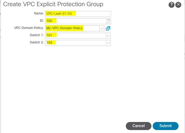
We just need to define the 2 leaf switches in the same VPC domain.
Fabric > Access policies > policies > switch > virtual port channel default > Select “+”
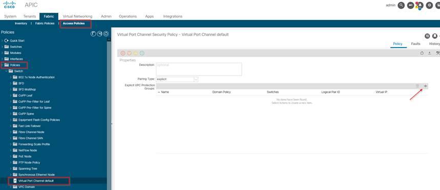
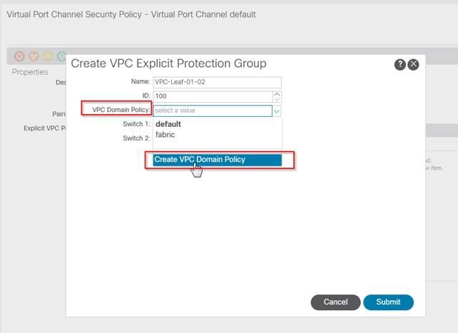
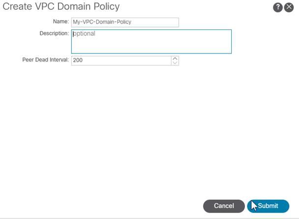
Submit
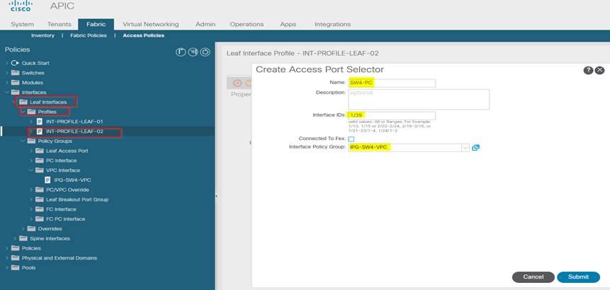
Now we need to create a VPC IPG in order to connect Leaf-01 and Leaf-02 to the SW4 in VPC domain
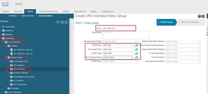
Next and Finish
Now we need to assign port 35 on Leaf-01 and Port 39 on Leaf-02 in the VPC IPG
We need to do that in the interface profile of Leaf-01 and Leaf-02, which is already created
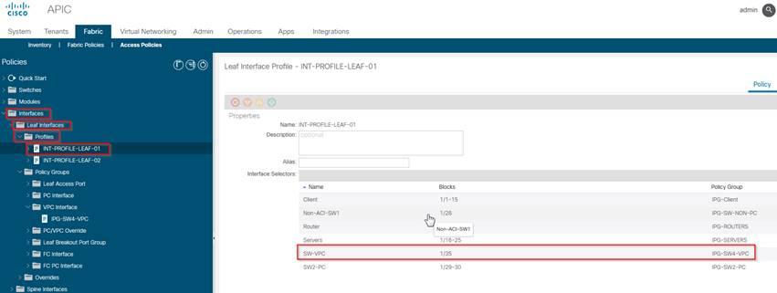
--------------------------------------------------------------------------------------------------------------------------------------------------------------------------------------
--------------------------------------------------------------------------------------------------------------------------------------------------------------------------------------
Vlan and Port Types
We create VLAN pool and assign the range of VLAN ID defined in the VLAN Pool to the ports
VLAN is required in ACI for backward compatibility with existing switching and end hosts connect to those for VLAN backed communication.
Within the ACI fabric the communication occurs using VXLAN by default
--------------------------------------------------------------------------------------------------------------------------------------------------------------------------------------
--------------------------------------------------------------------------------------------------------------------------------------------------------------------------------------
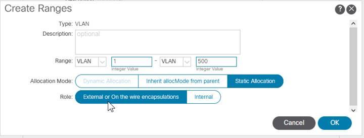
Configure VLAN Pools
Range of VLANs required [1-500] is divided into 3 separate pools
ACI Physical
L2 External
L3 External
The above pool will equally mapped with the port types
ACI Physical port
L2 External port
L3 External port
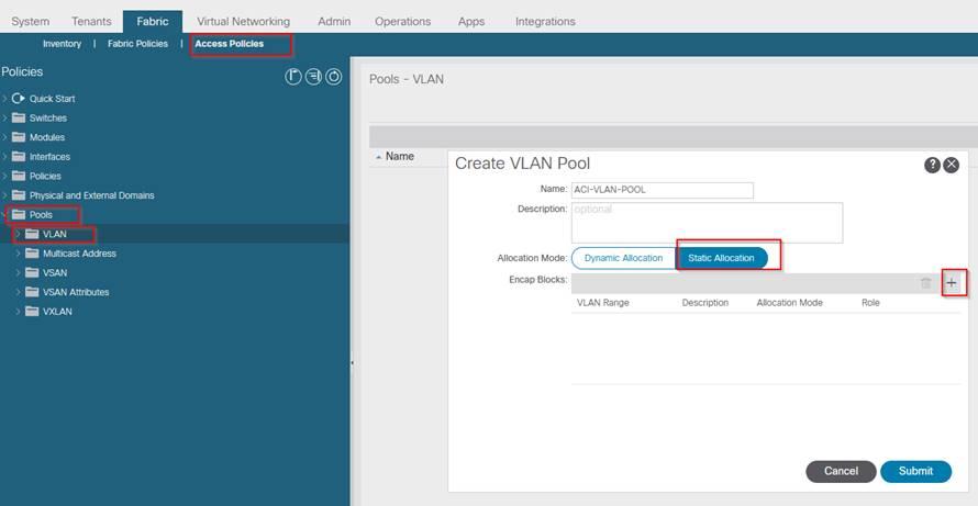
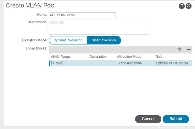
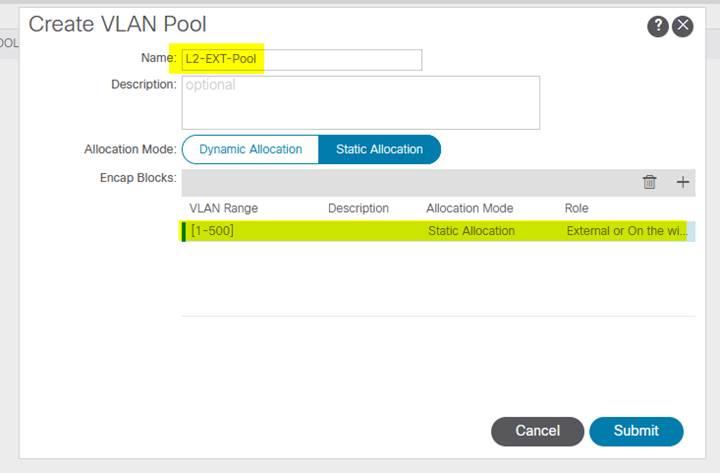
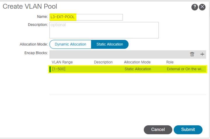
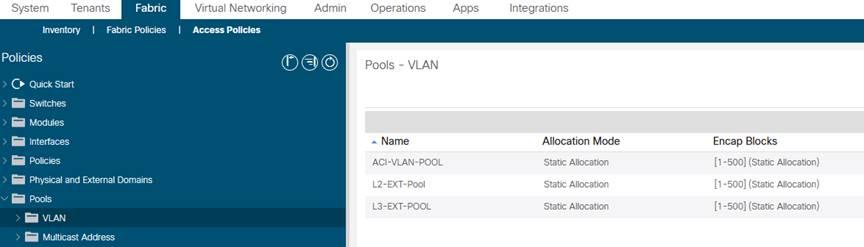
Fabric > Access Policies > Pools > VLAN and Select “Create VLAN Pool’
--------------------------------------------------------------------------------------------------------------------------------------------------------------------------------------
--------------------------------------------------------------------------------------------------------------------------------------------------------------------------------------
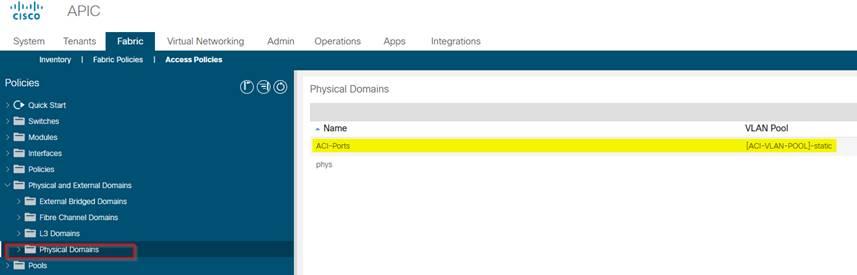
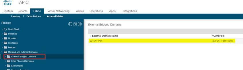
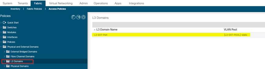
Configure Domains
Also referred as Port types
We need to link the VLAN Pools created in previous step to the domain – physical domain and external domain
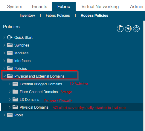
Creating VLAN to Domain mappings(port types)
--------------------------------------------------------------------------------------------------------------------------------------------------------------------------------------
--------------------------------------------------------------------------------------------------------------------------------------------------------------------------------------
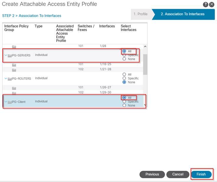
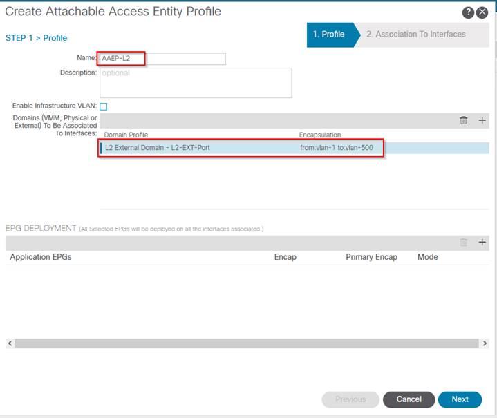
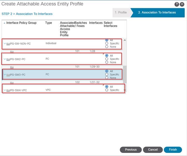
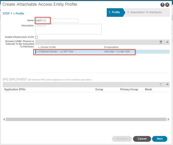
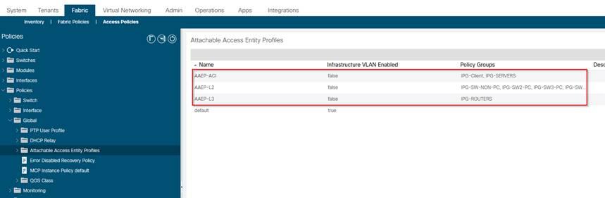
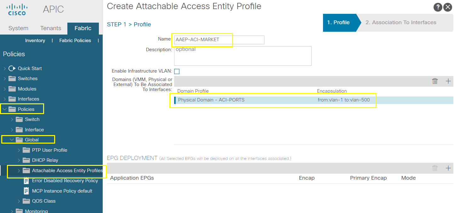
Configure AAEPs
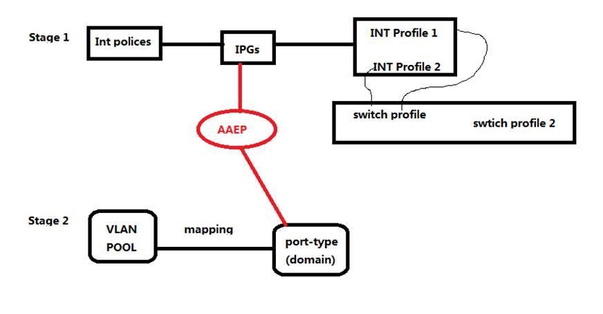
Attachable Access Entity Profile (AAEP)
AAEP is a stitching mechanism which links IPGs assigned to ports with the ACI port types assigned with VLAN pools
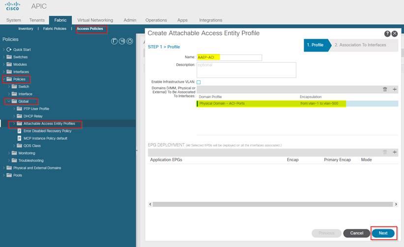
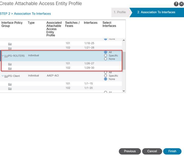
With the above steps we have associated the leaf access ports with the right port types and allowed vlans
We have the physical Infra ready and this whole thing is known as Access provisioning.
--------------------------------------------------------------------------------------------------------------------------------------------------------------------------------------
--------------------------------------------------------------------------------------------------------------------------------------------------------------------------------------
Access Provisioning Flow Chart
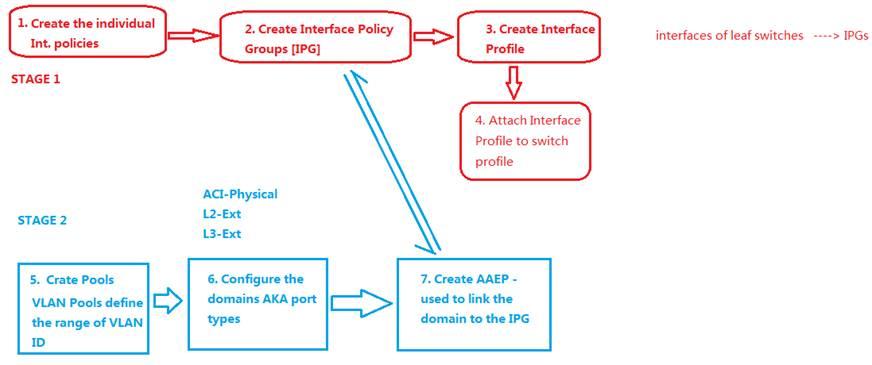
From <https://scotiabank-my.sharepoint.com/personal/cheng_zhong_scotiabank_com/Documents/Desktop/AC2.docx>
--------------------------------------------------------------------------------------------------------------------------------------------------------------------------------------
--------------------------------------------------------------------------------------------------------------------------------------------------------------------------------------
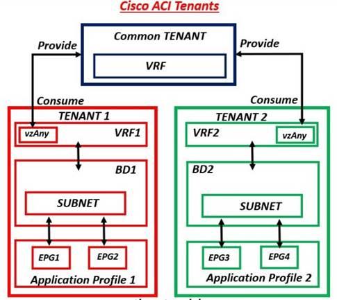
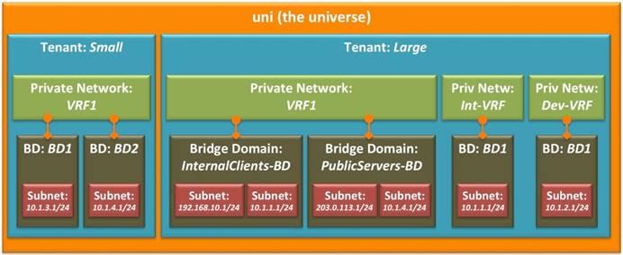
Overview Tenant, VRFs, DBs & SVIs
Default tenant
INFRA
MGMT
Common
Objects – ACL/Filters
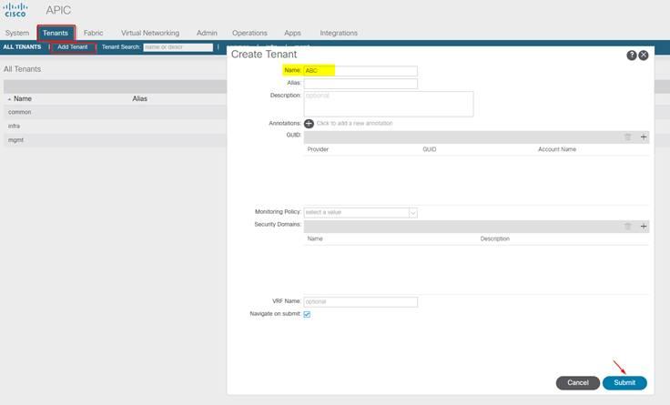
Create Tenant
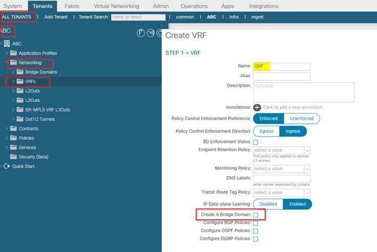
Create VRFs
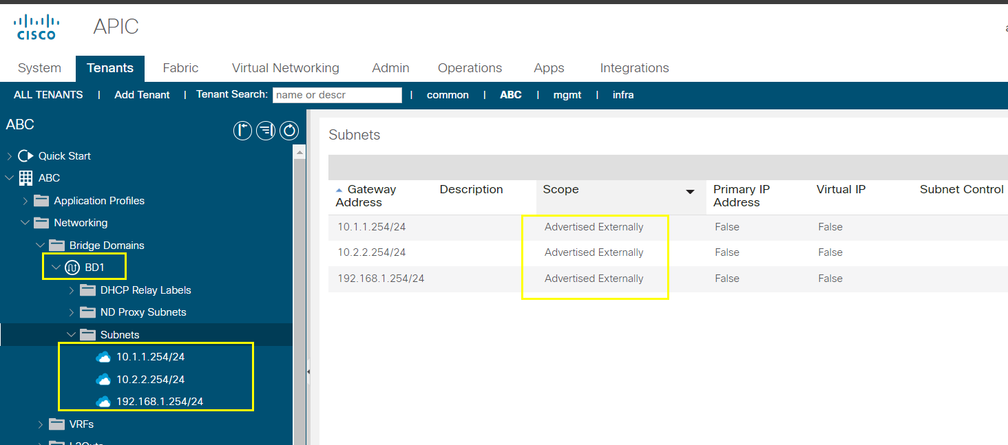
Create Bridge Domains (VXLAN) and SVIs
--------------------------------------------------------------------------------------------------------------------------------------------------------------------------------------
--------------------------------------------------------------------------------------------------------------------------------------------------------------------------------------
Create Tenant, VRFs, BDs & SVIs
Tennant: generally a company using the ACI DC Infra.
# Create a Tenant
Create VRF under the Tenant ABC
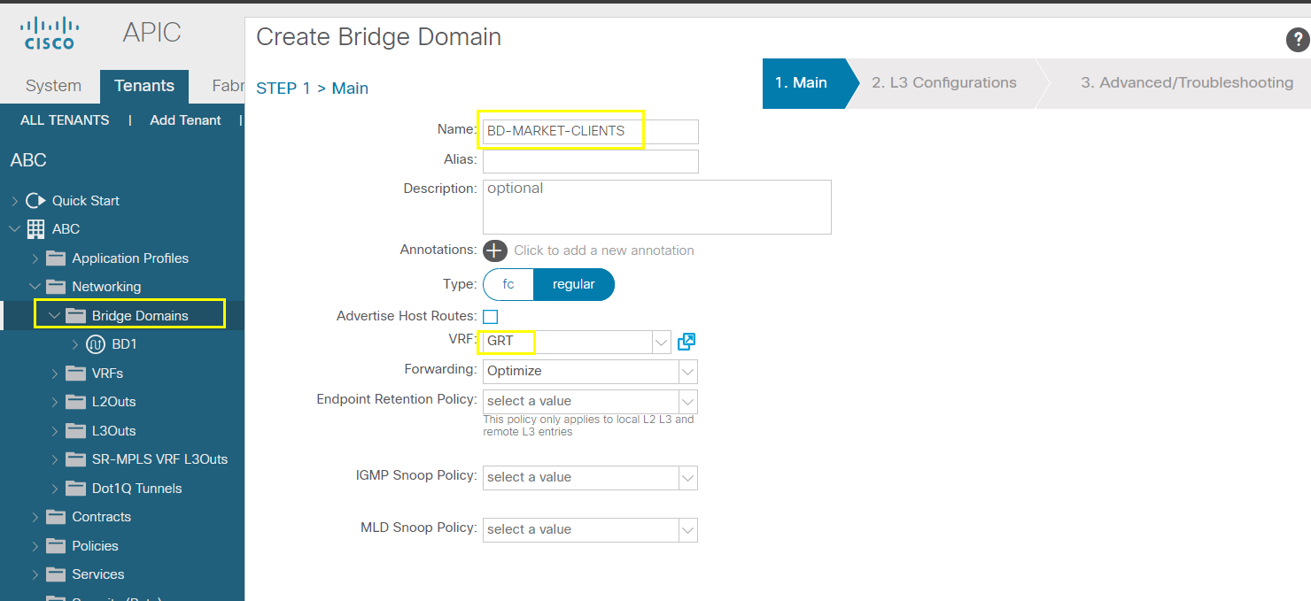
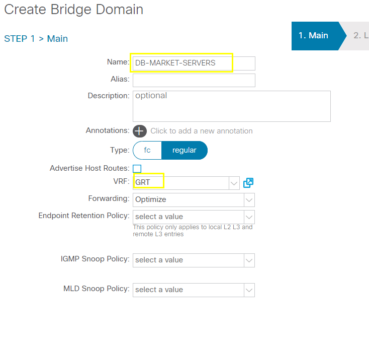
Crate Bridge Domain
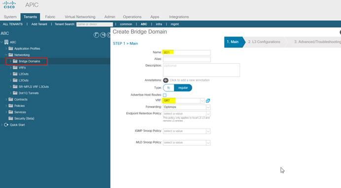
Next
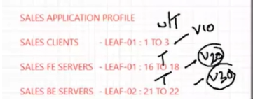
Client – 10.1.1.0/24 - Leaf-01 : 1 To 3
Front end servers – 10.2.2.0/24 – Leaf-01: 16 To 18
Back end servers – 192.168.1.0/24 – Leaf-02: 21 To 22
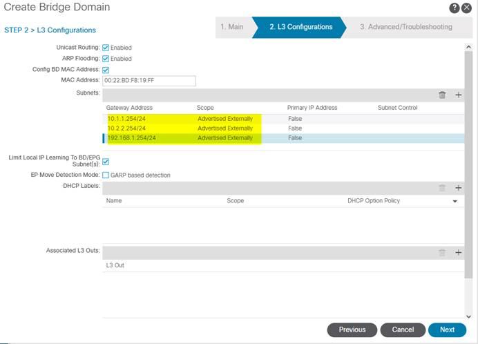
Next
Nothing in step 3
Finish
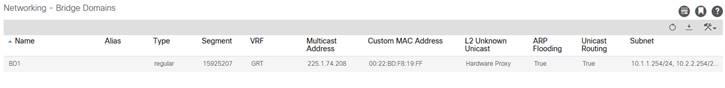
Multicast IP is automatically created.
You will be in L3 configuration page where you need to define the subnets as per your topology plan.
Notice the VNI segment ID value which is automatically generated along the M/C IP and MAC used by VXLAN.
--------------------------------------------------------------------------------------------------------------------------------------------------------------------------------------
--------------------------------------------------------------------------------------------------------------------------------------------------------------------------------------
Application Provisioning Overview
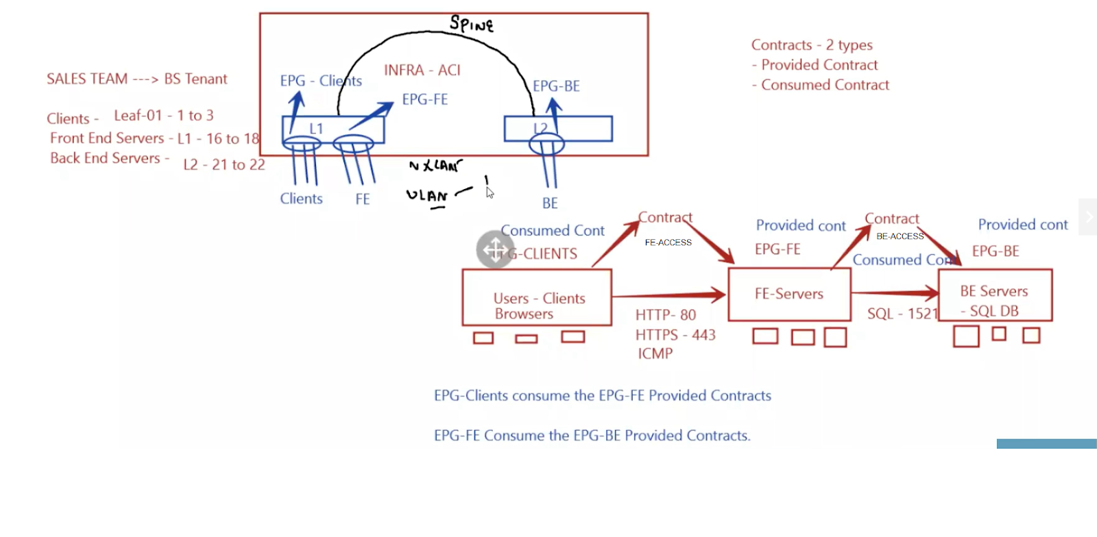
Intra - EPG Allow
Inter EPG not allowed default
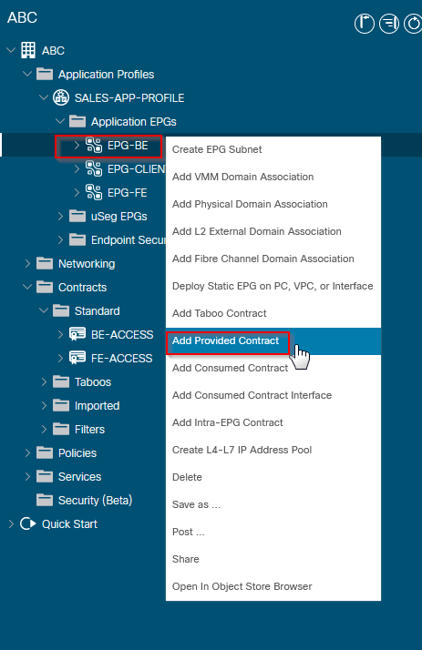
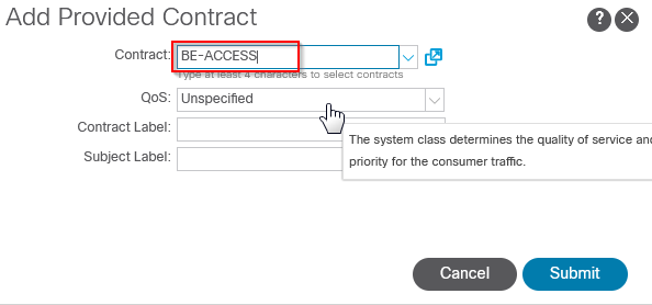
'Providing' a Contract means providing a service (like TCP/80 inbound)
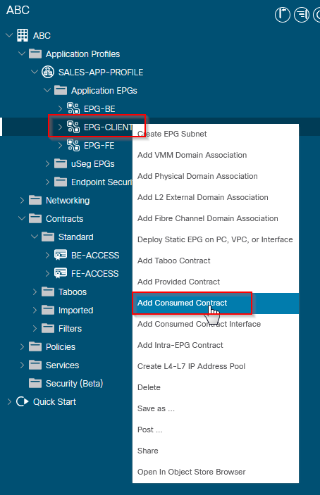
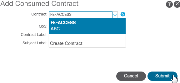
'Consuming' a contract allows an EPG to connect to a provided service
--------------------------------------------------------------------------------------------------------------------------------------------------------------------------------------
--------------------------------------------------------------------------------------------------------------------------------------------------------------------------------------
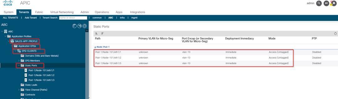
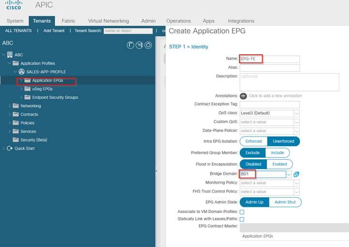
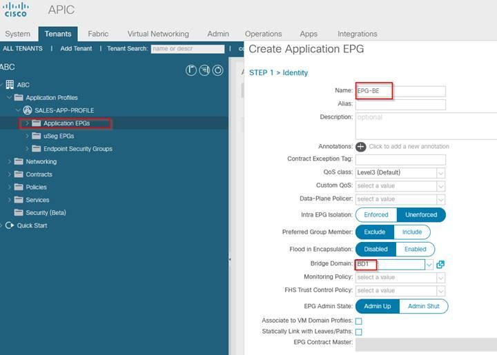
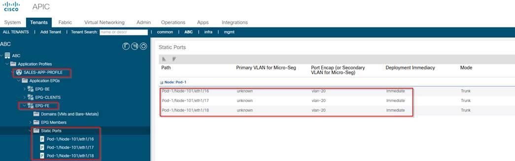
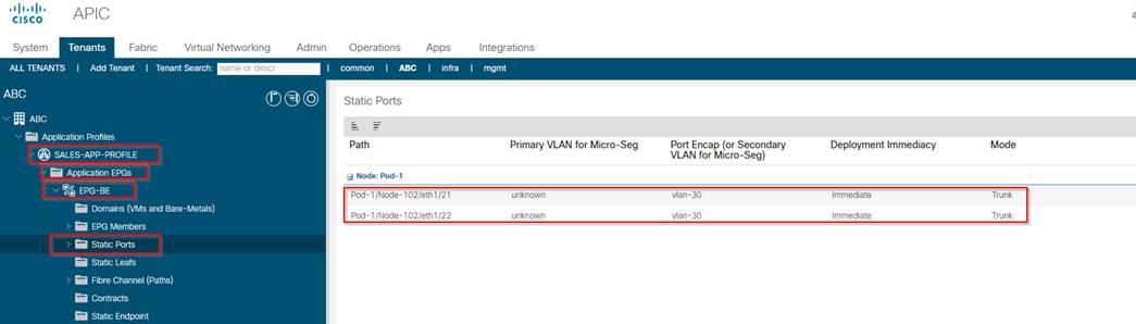
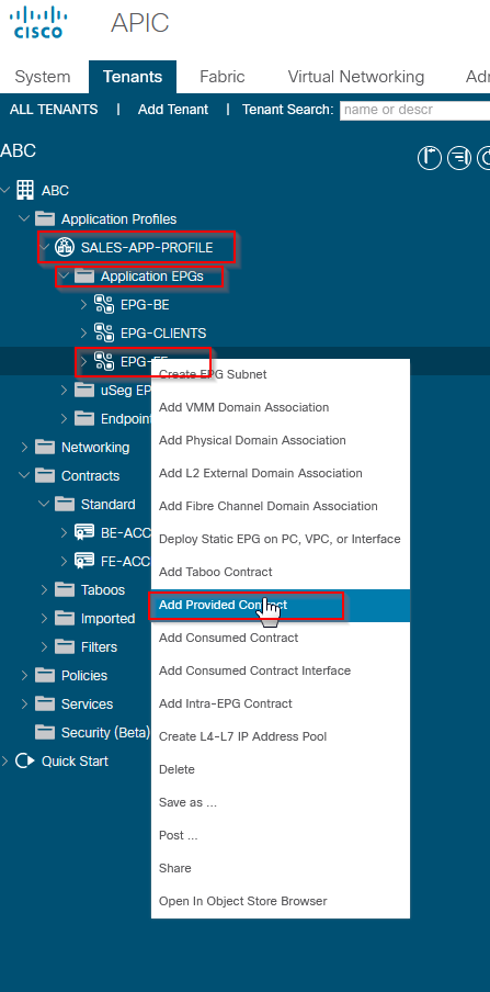
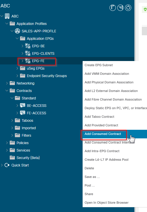
Creating the Application Profile, EPGs and Assign the Ports to the EPGs
--------------------------------------------------------------------------------------------------------------------------------------------------------------------------------------
--------------------------------------------------------------------------------------------------------------------------------------------------------------------------------------
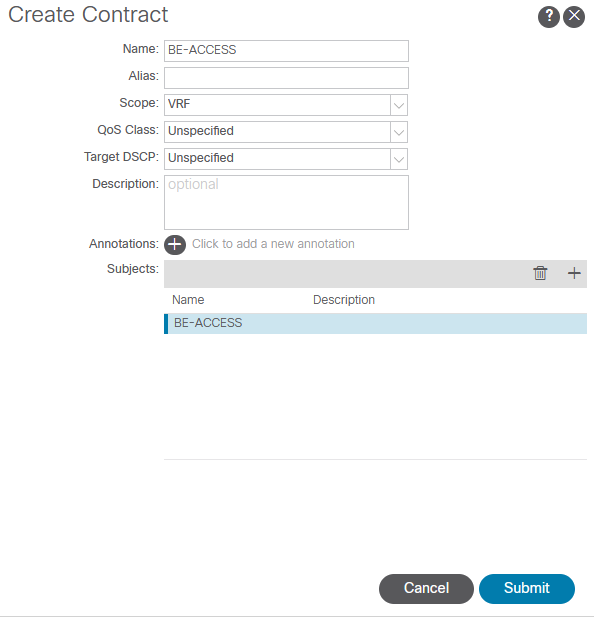
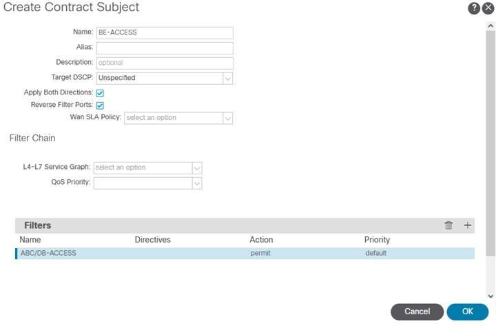
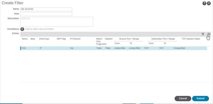
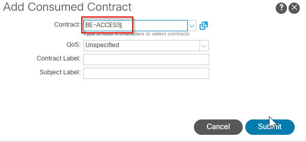
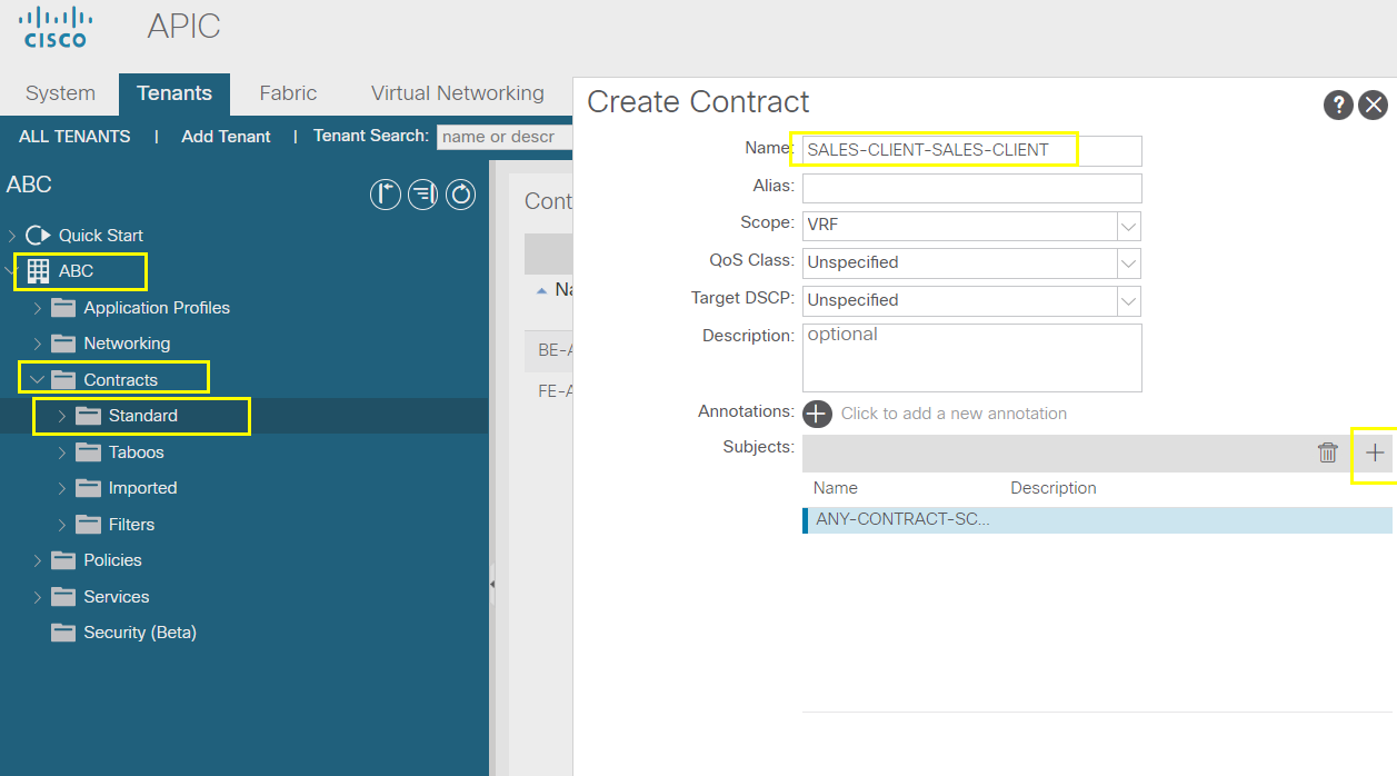
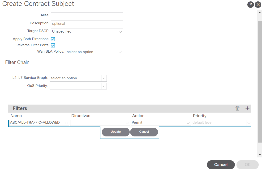
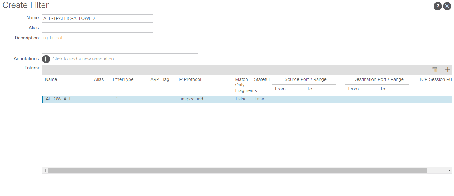
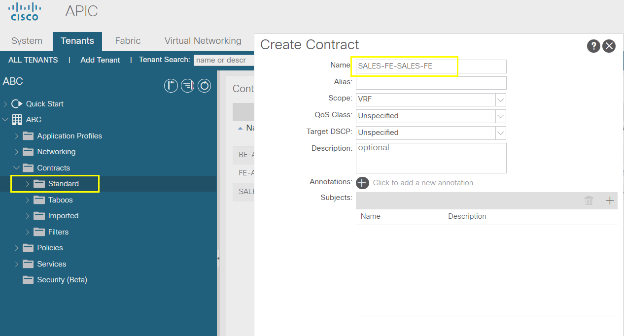
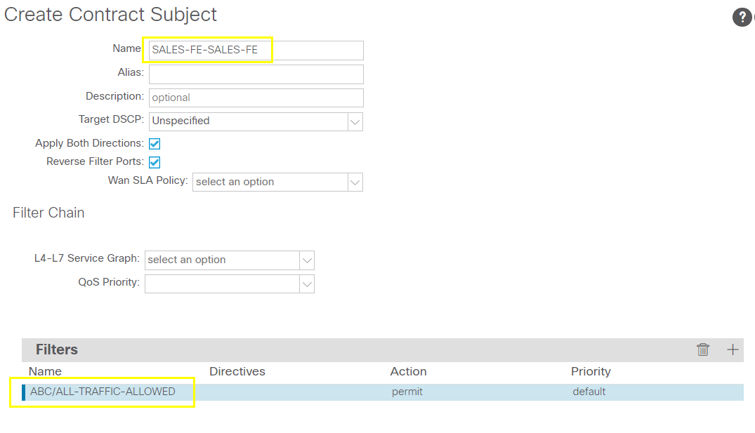
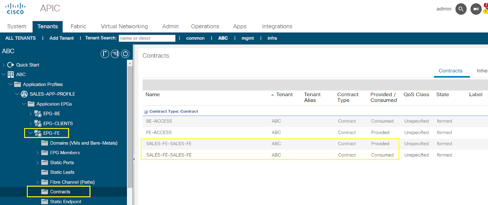
Creating and Provisioning the Contracts, Subjects and Filters
FE-ACCESS
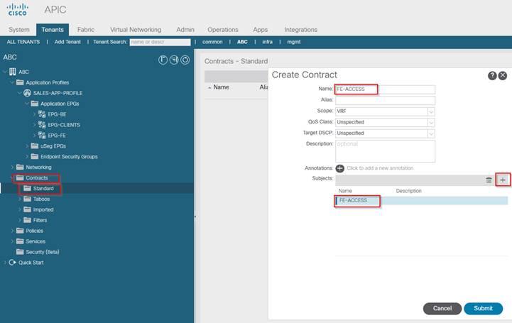
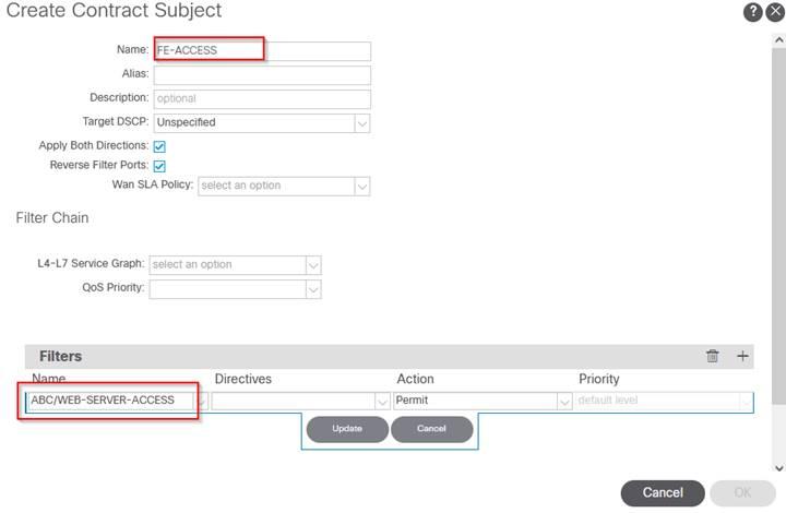
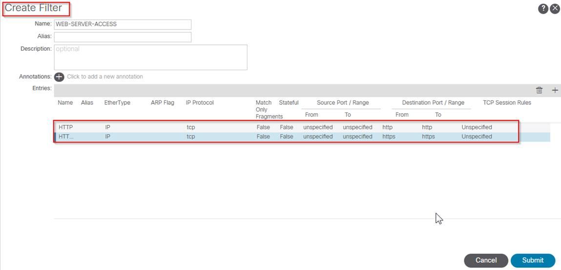
BE-ACCESS

--------------------------------------------------------------------------------------------------------------------------------------------------------------------------------------
--------------------------------------------------------------------------------------------------------------------------------------------------------------------------------------
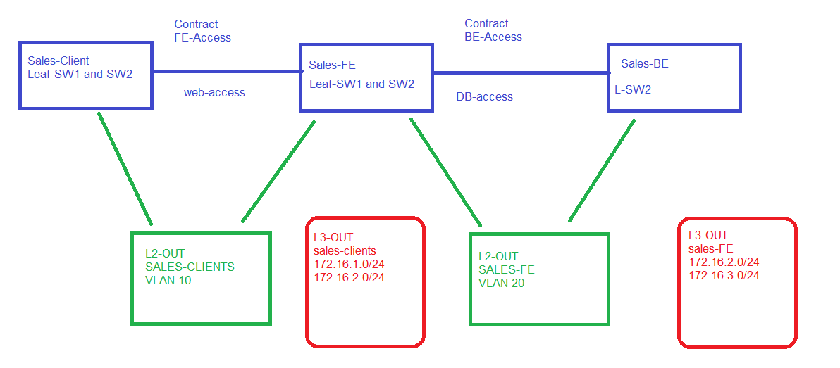
L2-OUT Overview
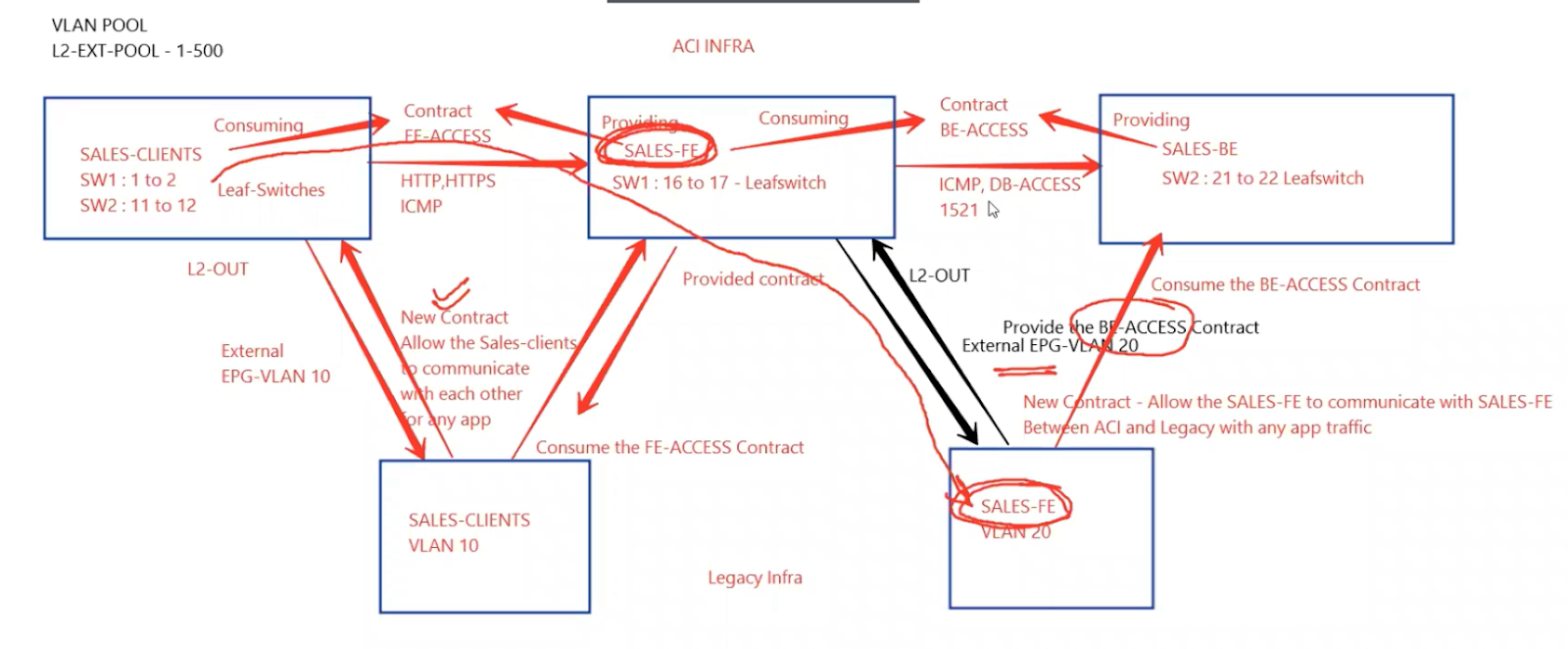
Sales-client connected between ACI switches to non-aci switches must be able to communicate with each other.
Likewise sales-FE between ACI and Non-ACI switches should communicate with each other
Sales Client -VLAN 10
Sales FE - VLAN 20
Note: all basic setup is already provisioned so far using the access provisioning, tenant provisioning and application provisioning steps
--------------------------------------------------------------------------------------------------------------------------------------------------------------------------------------
--------------------------------------------------------------------------------------------------------------------------------------------------------------------------------------
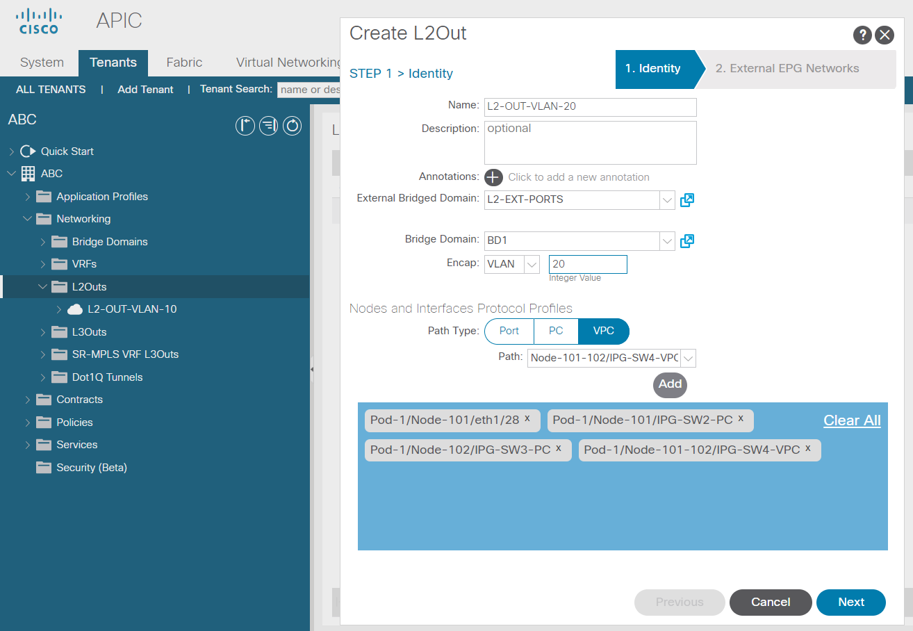
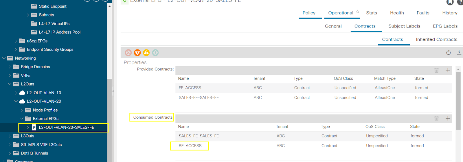
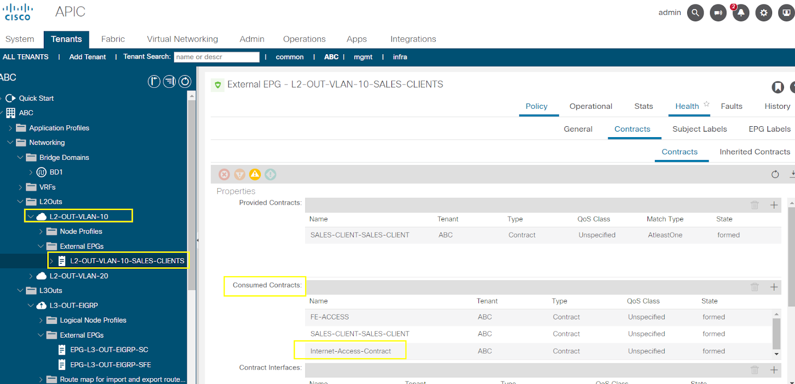
Configure L2-OUT & Contracts
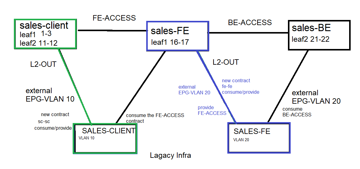
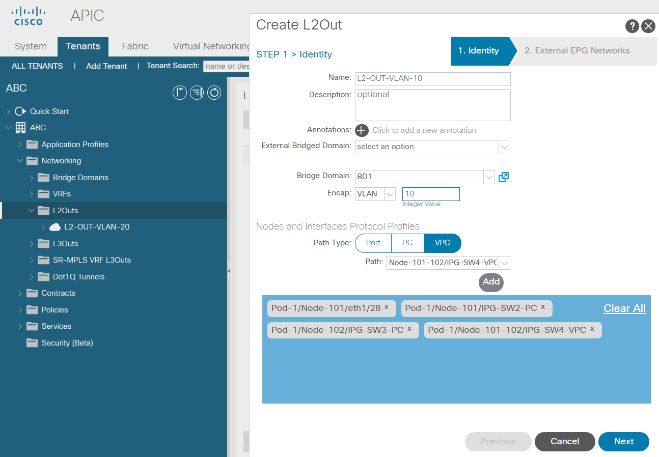
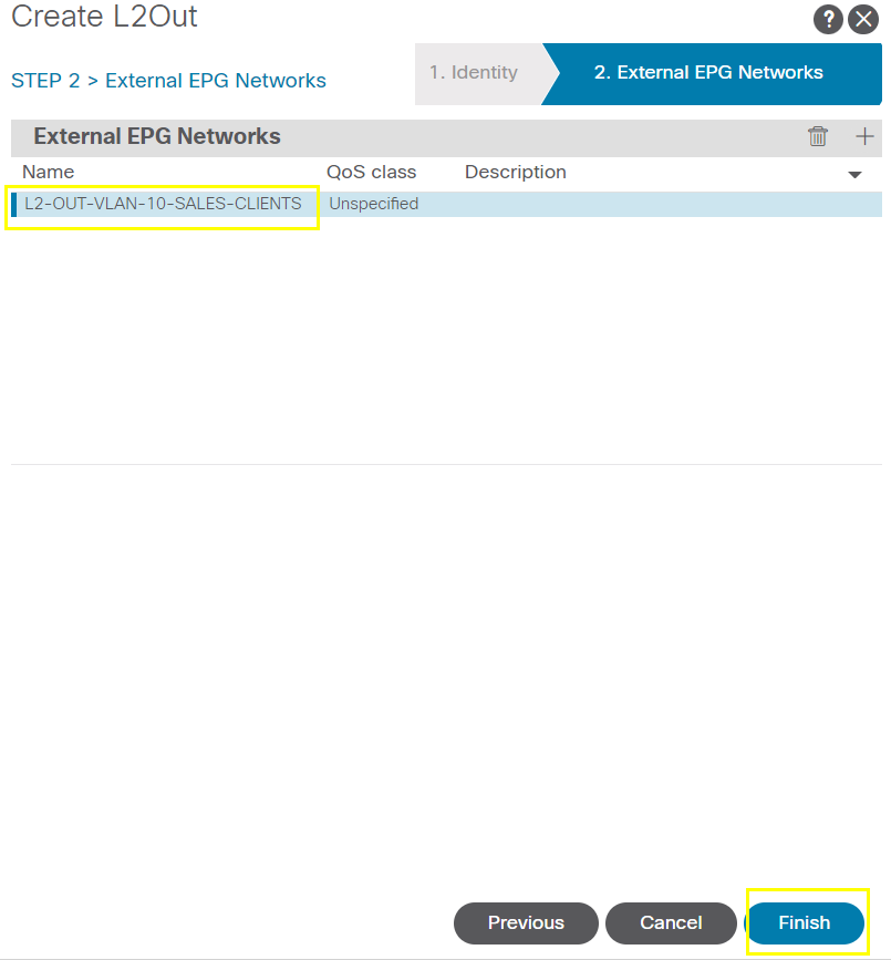
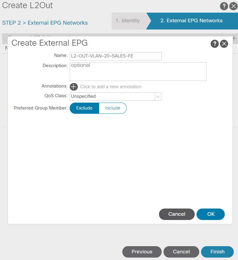
We need to create contract for the external sales-clients to consume the ACI Sales FE-ACCESS contract
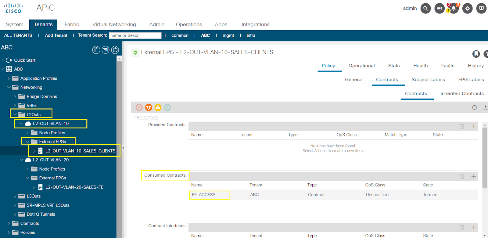
Now let allow sales-clients of ACI to communicate with external sales-clients for any application traffic in VLAN 10

Now we need to provide ACI sales-clients access to external Sales-FE in VLAN 20

Now lets allow the external sales-fe to consume the ACI BE-ACCESS Contract
--------------------------------------------------------------------------------------------------------------------------------------------------------------------------------------
--------------------------------------------------------------------------------------------------------------------------------------------------------------------------------------
L3-OUT Overview
--------------------------------------------------------------------------------------------------------------------------------------------------------------------------------------
--------------------------------------------------------------------------------------------------------------------------------------------------------------------------------------
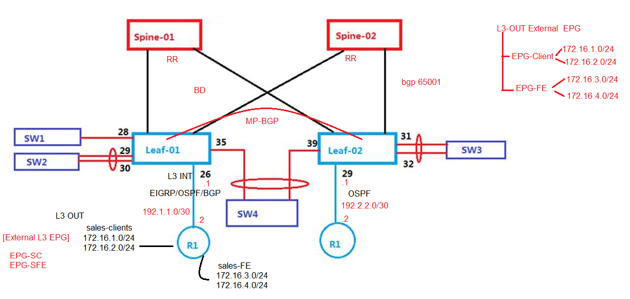
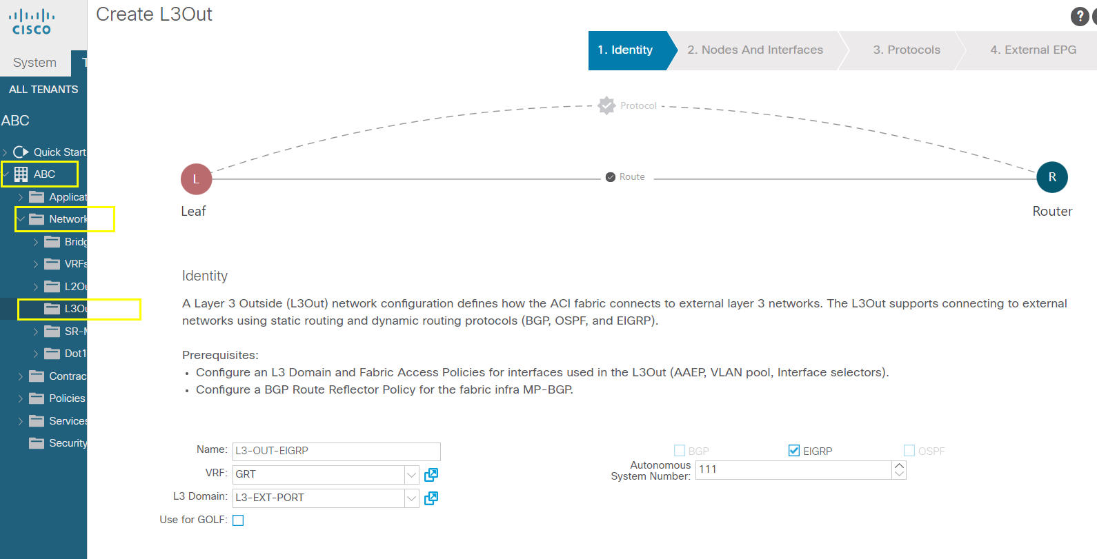
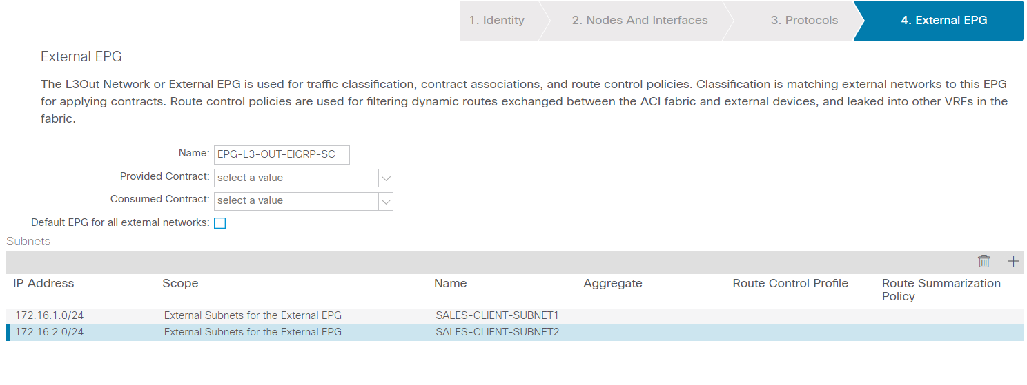
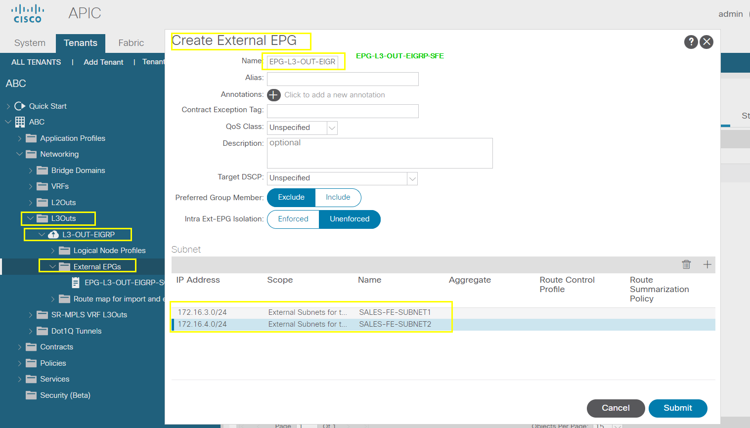
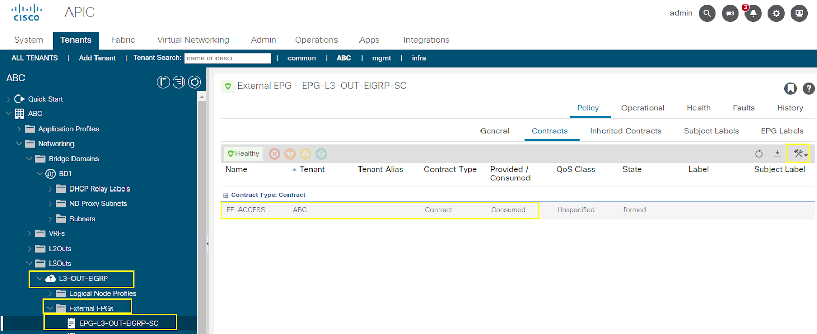
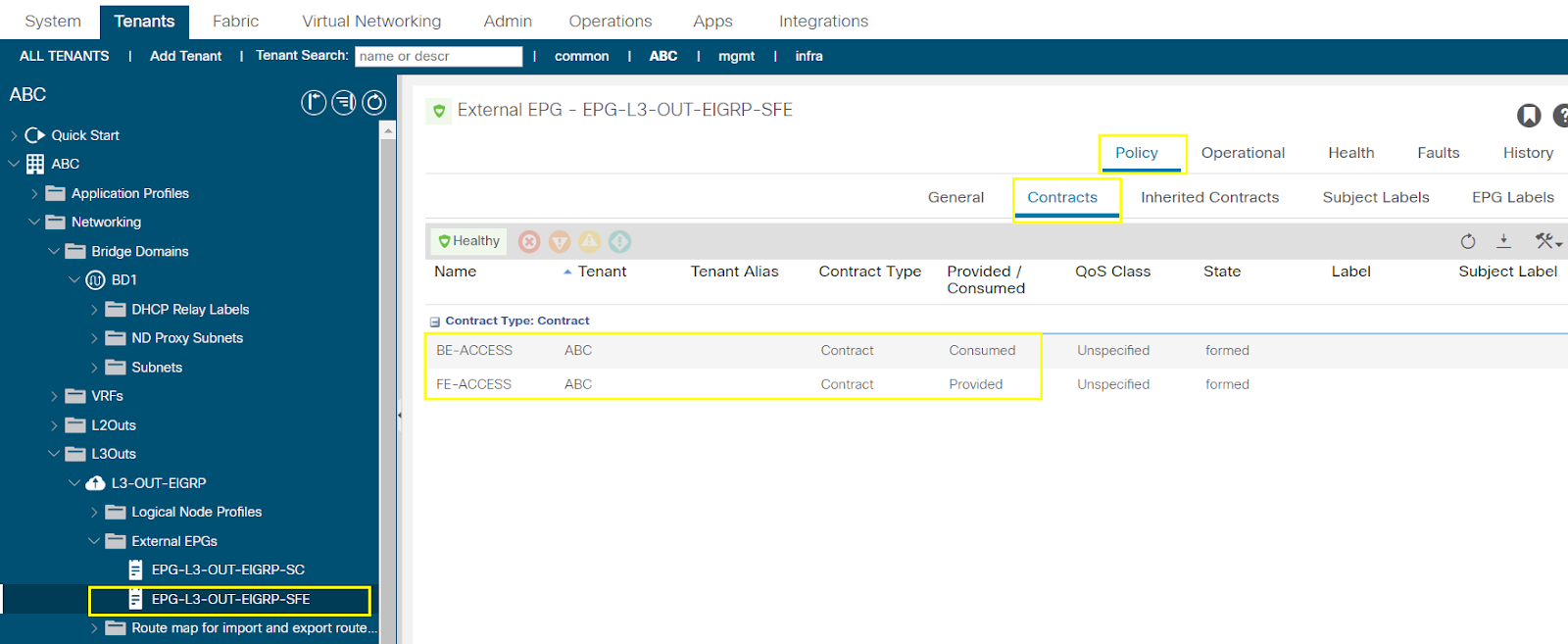
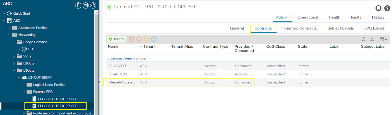
Configure L3-OUT, EPGs & Contracts
A Layer 3 Outside (L3Out) network configuration defines how the ACI fabric connects to external layer 3 networks. The L3Out supports connecting to external networks using static routing and dynamic routing protocols (BGP, OSPF, and EIGRP).
Prerequisites:
Configure an L3 Domain and Fabric Access Policies for interfaces used in the L3Out (AAEP, VLAN pool, Interface selectors).
Configure a BGP Route Reflector Policy for the fabric infra MP-BGP.
Setup up MP-BGP in the fabric - done while doing the initialization of the fabric
AS Number 65001
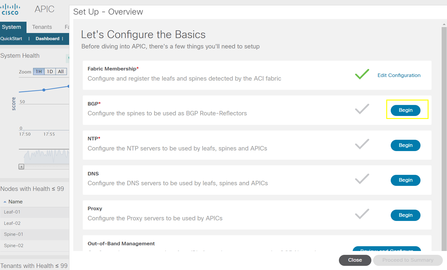
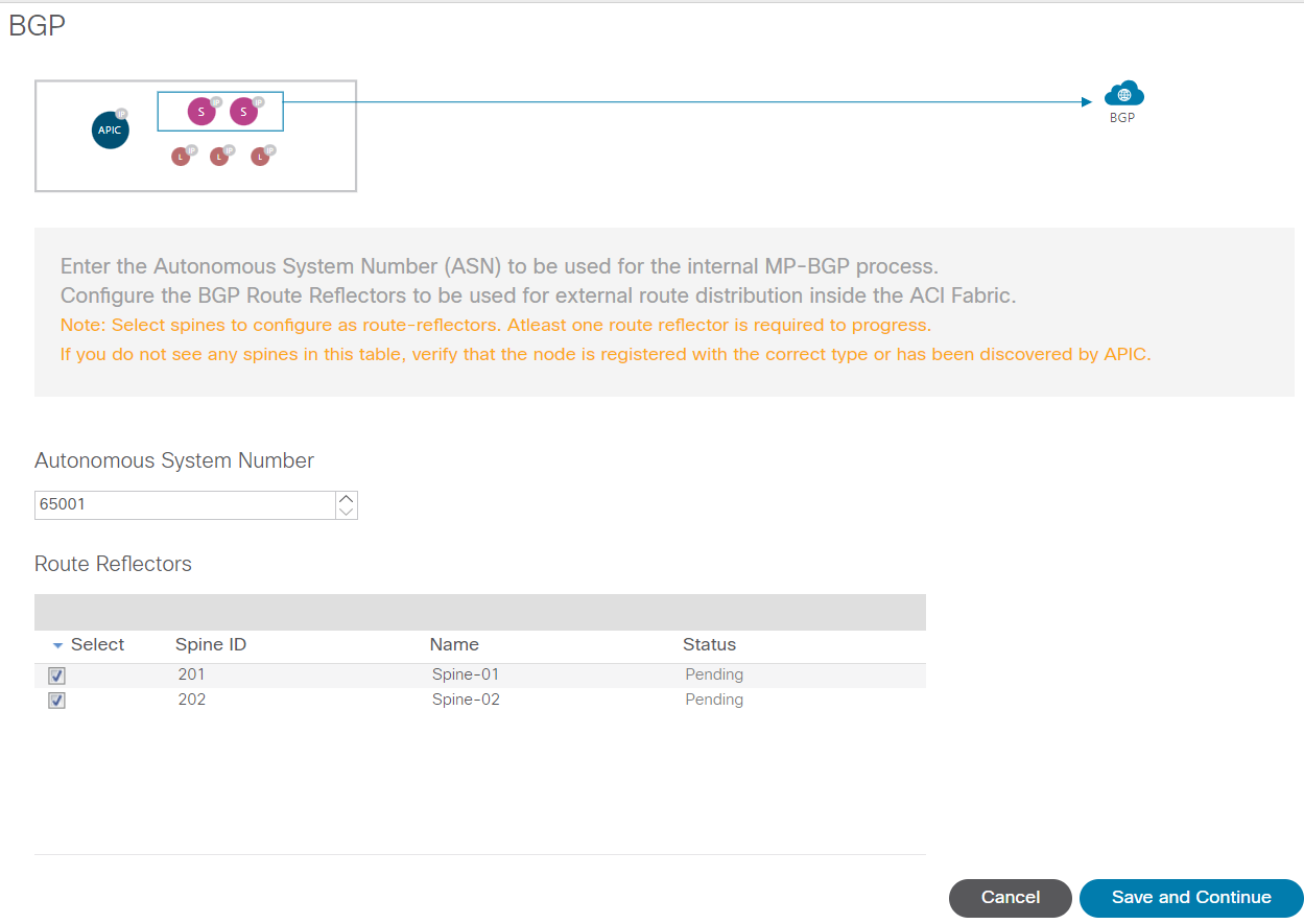
Yes/submit changes
While begin first time wizard - enable MP-BGP by selecting both the spines as RR which creates a BGP-default policy.
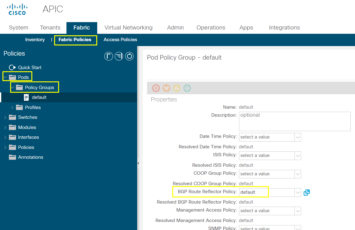
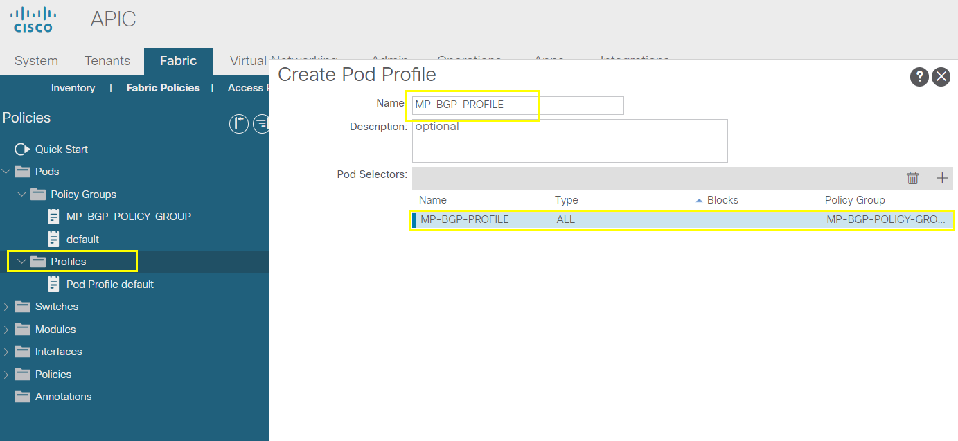
Now we need to call this BGP default policy in the Pod Profile and call the Pod profile in Policy Group
# Configure EIGRP between Leaf-01 and the R1 connected to Port 26 on the Leaf-01
R1 - Sales Clients : 172.16.1.0/24, 172.16.2.0/24
- Sales FE : 172.16.3.0/24, 172.16.4.0/24
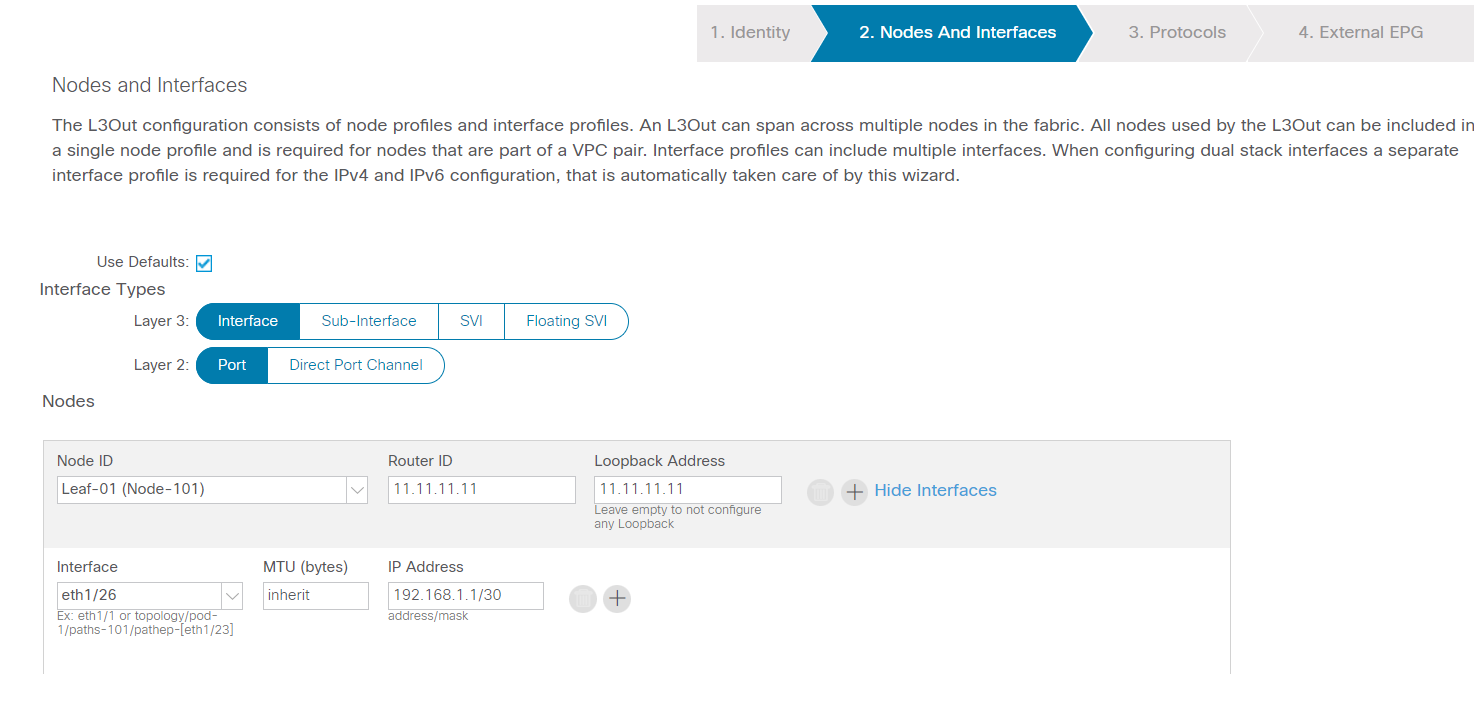
Configure EIGRP in the fabric: define the EIGRP node features, interface policy
Next
Next
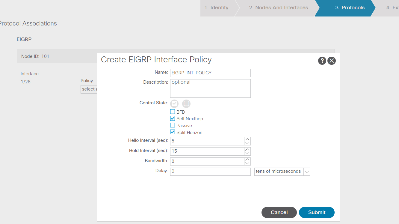
Submit
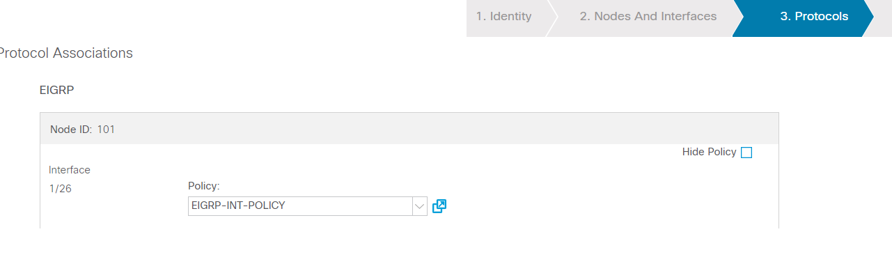
Next
Finish
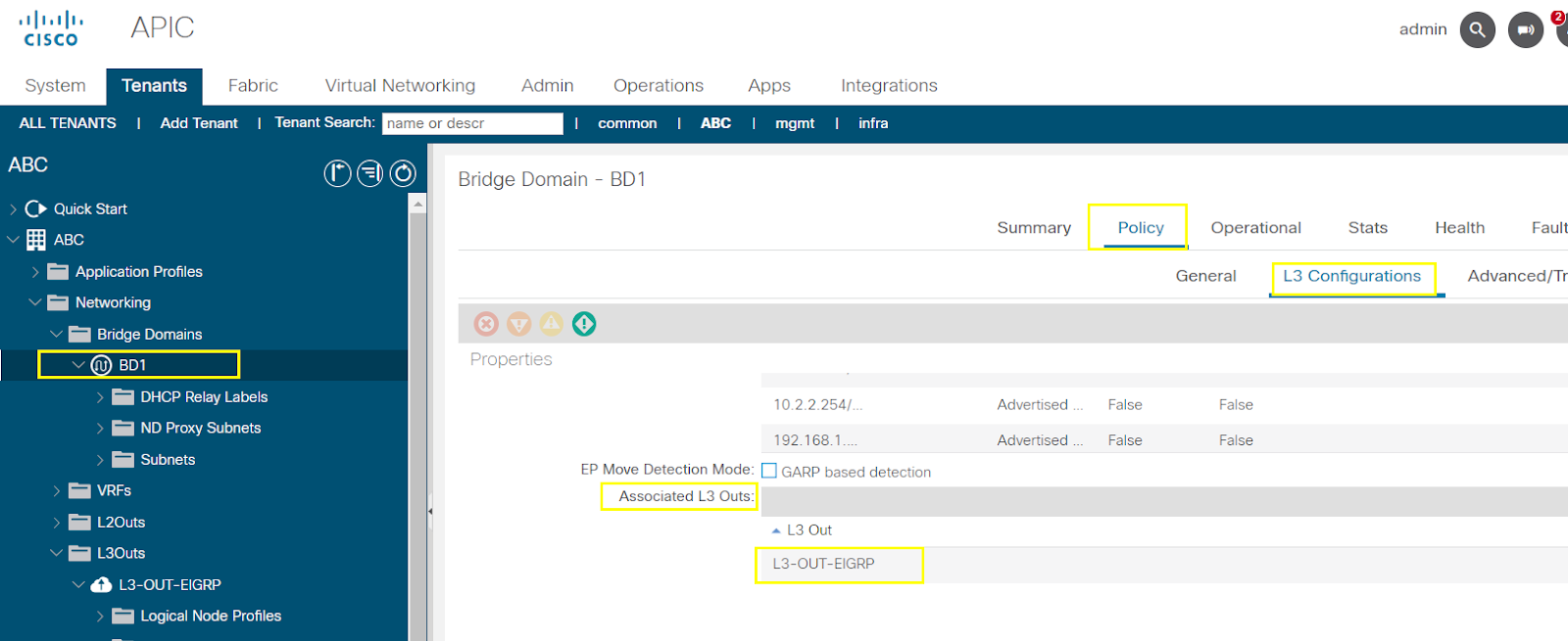
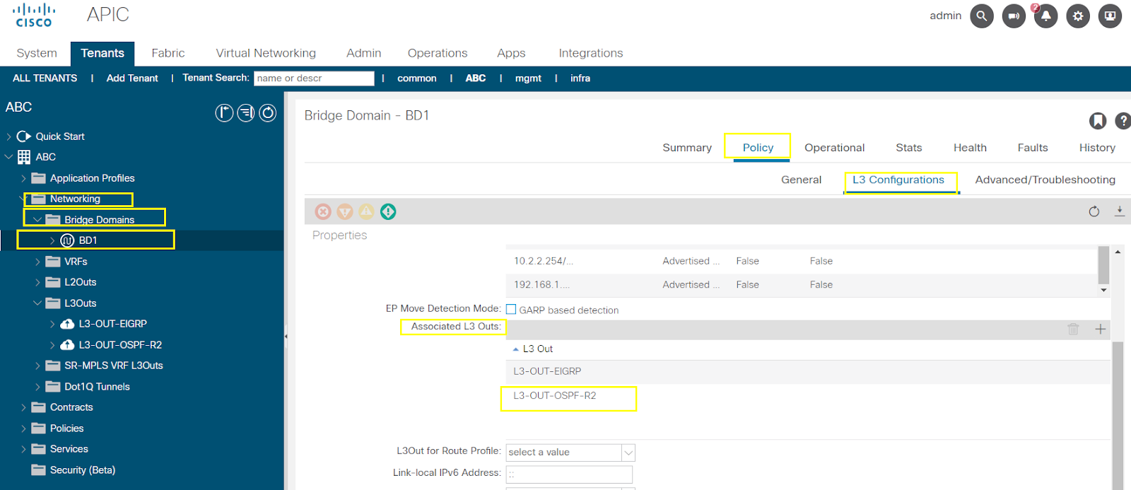
Link the ACI bridge domain with the L3-OUT-EIGRP
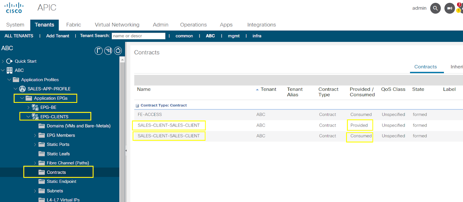
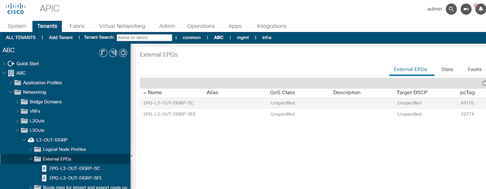
Now we need to apply contracts for each EPG
EPG-SALES-CLIENT --- Consume (FE-ACCESS)
EPG-SALES-FE --- Provide (FE-ACCESS), Consume (BE-ACCESS)
--------------------------------------------------------------------------------------------------------------------------------------------------------------------------------------
--------------------------------------------------------------------------------------------------------------------------------------------------------------------------------------
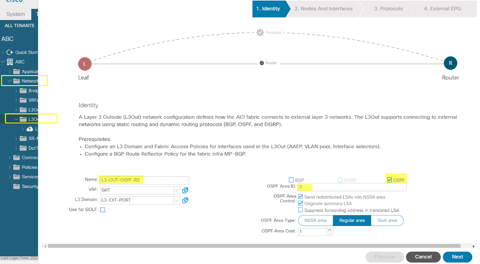
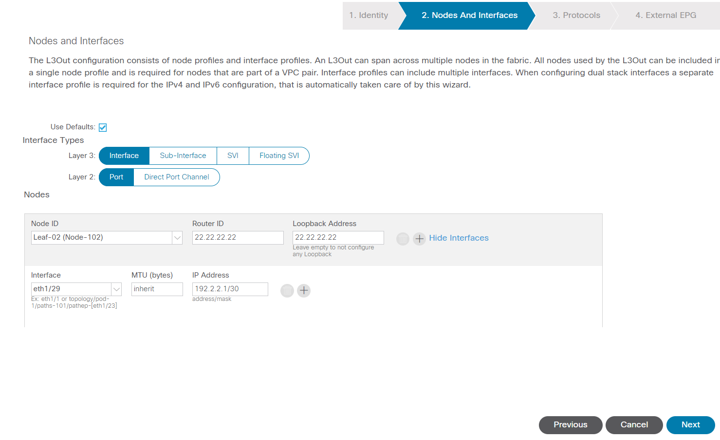
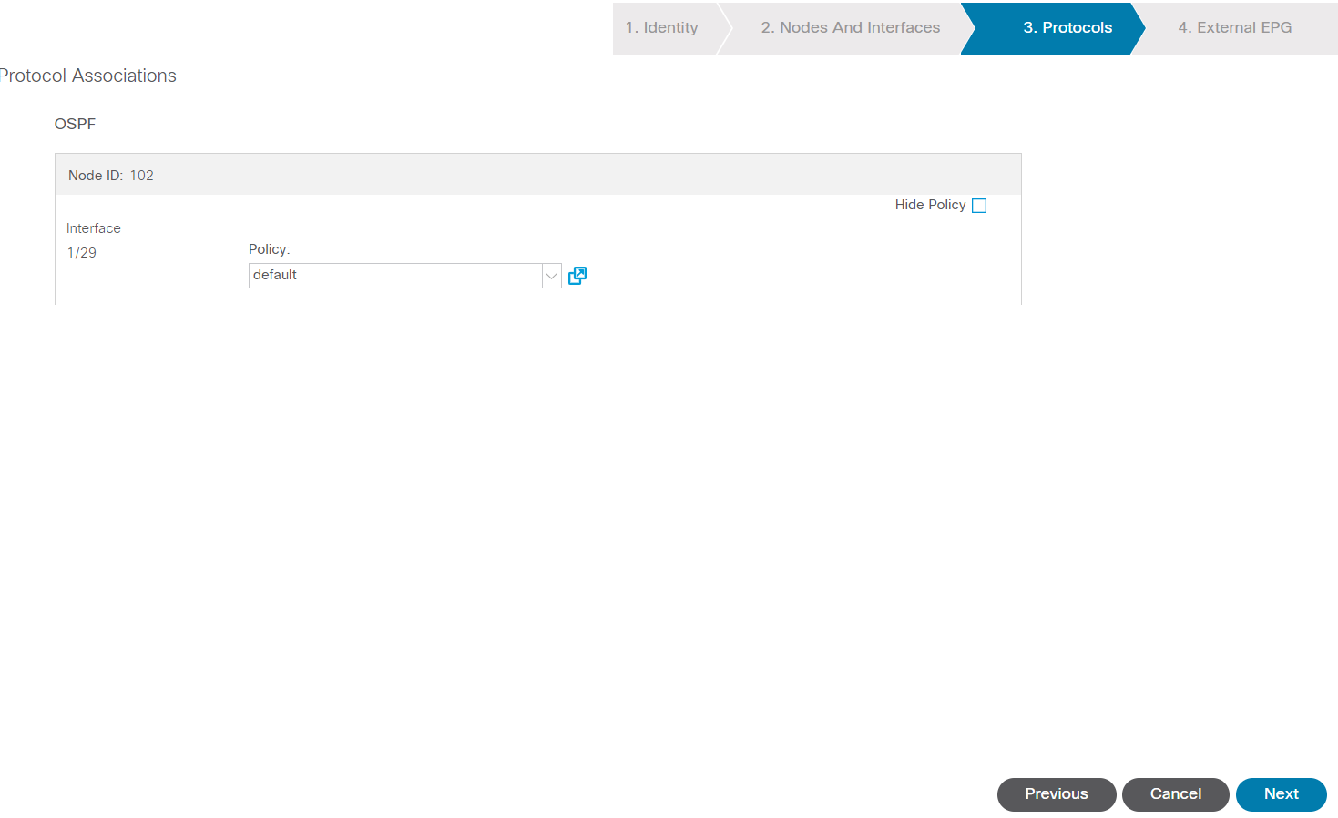
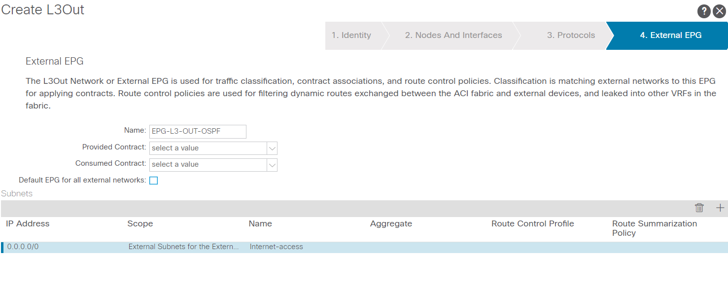
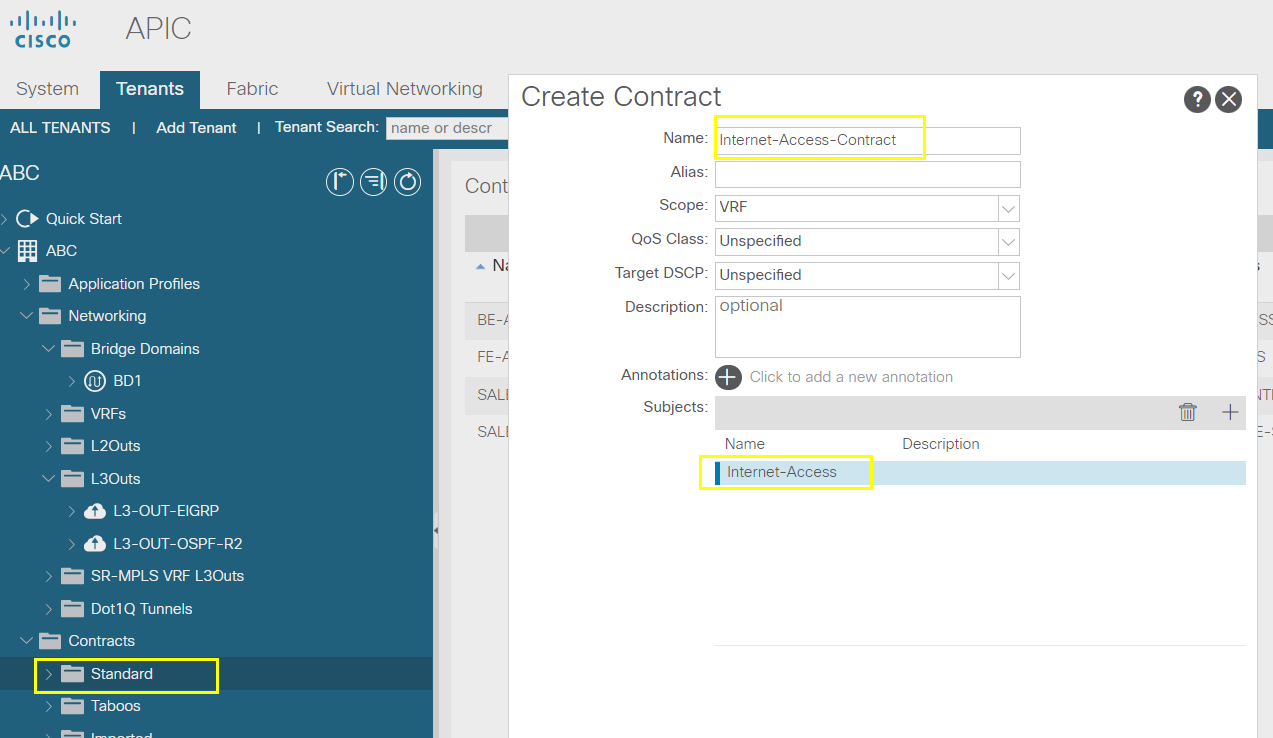
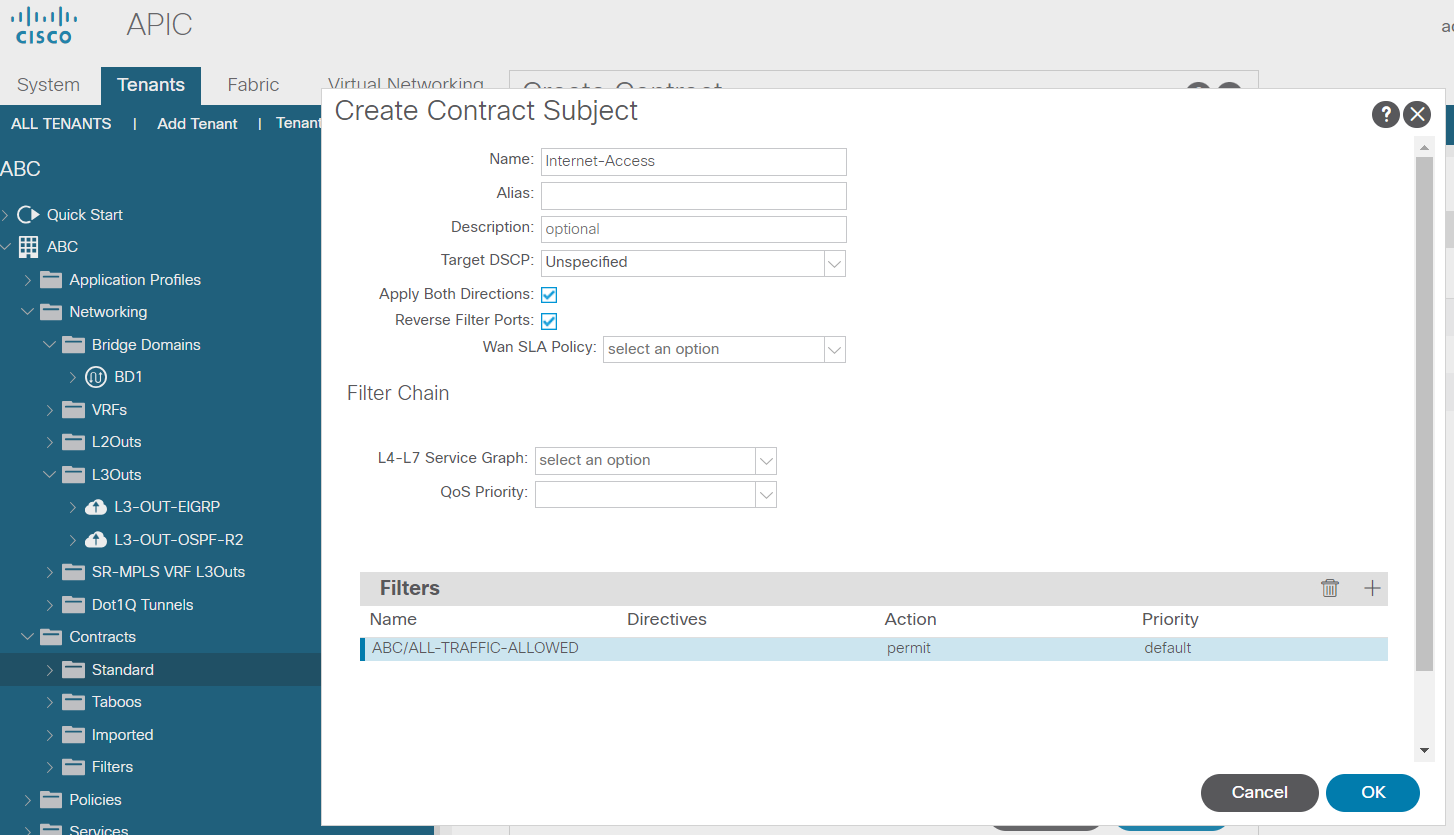
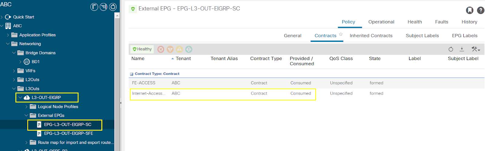
Configure L3-OUT using OSPF
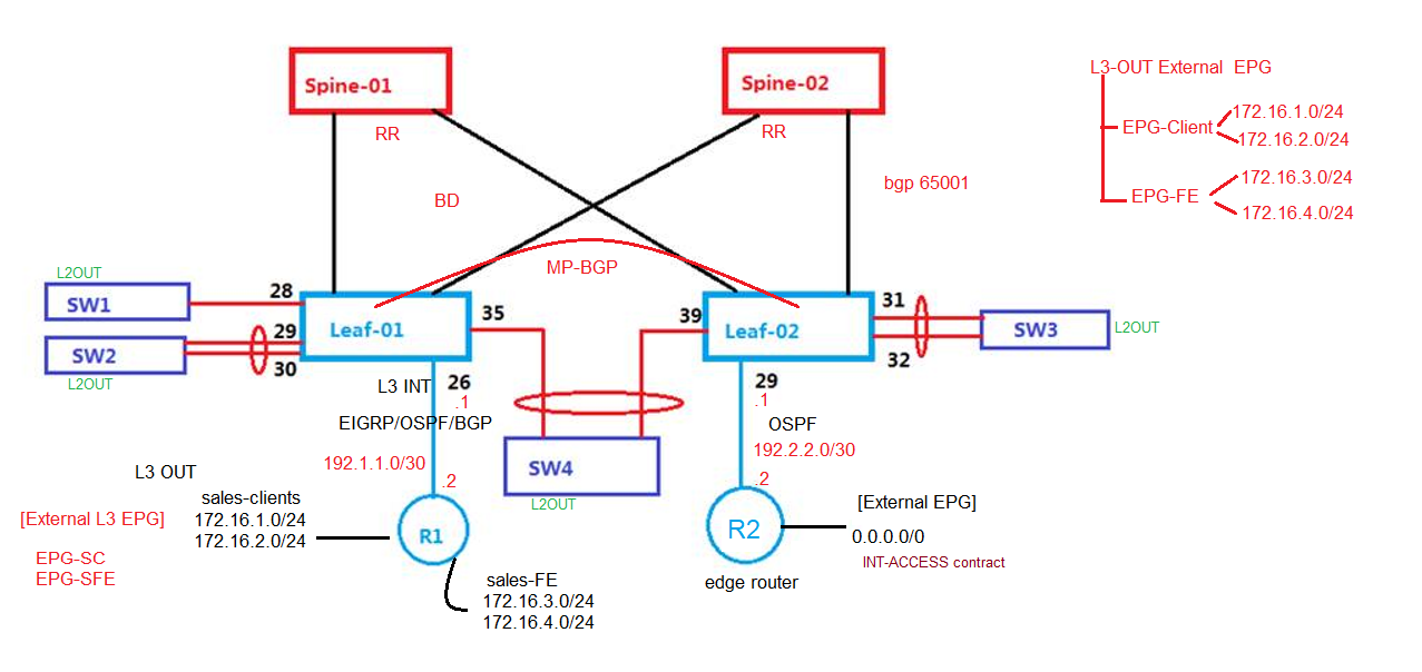
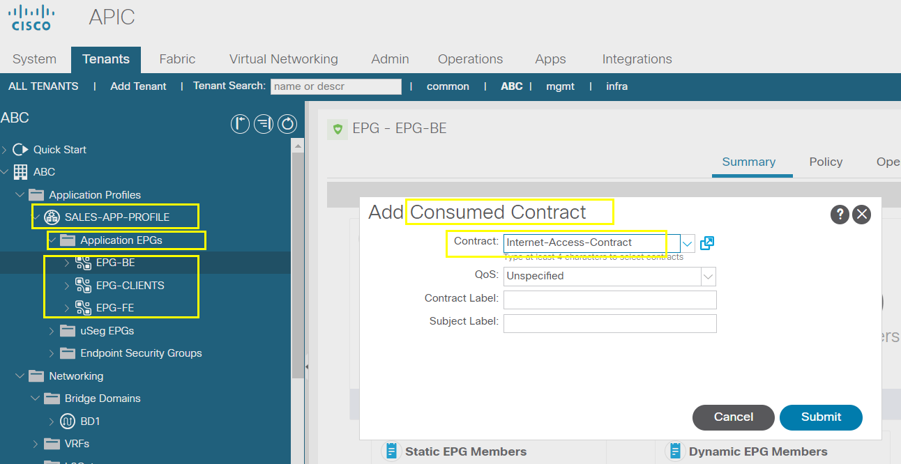
Configure OSPF as L3 OUT to provide Internet Access to all EPGs
L2 EPGs & L3 EPGs, ACI EPGs
-- create a separate contract : Internet Contract, 0.0.0.0/0 permit any
Steps are similar to EIGRP steps
Next
Next
Finish
Also can associated with VRF if have multiple BDs
Submit
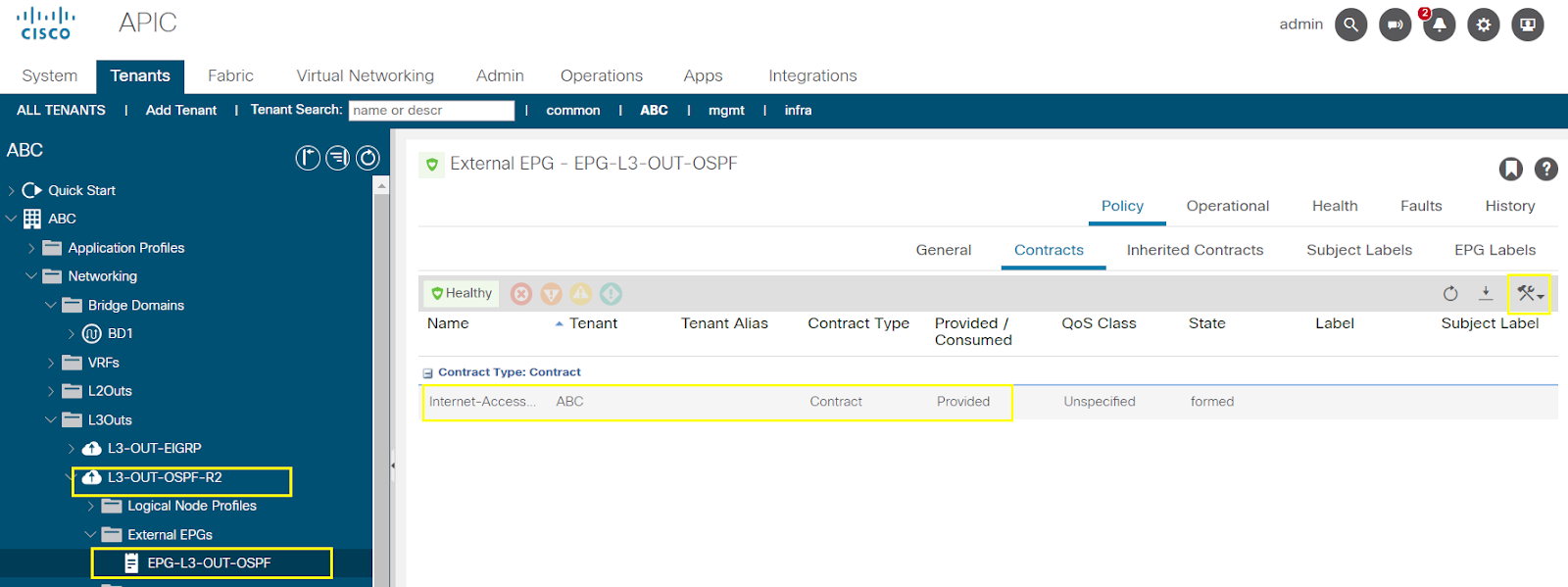
L3 OUT EPG
L2 OUT External EPG
ACI EPG
--------------------------------------------------------------------------------------------------------------------------------------------------------------------------------------
--------------------------------------------------------------------------------------------------------------------------------------------------------------------------------------
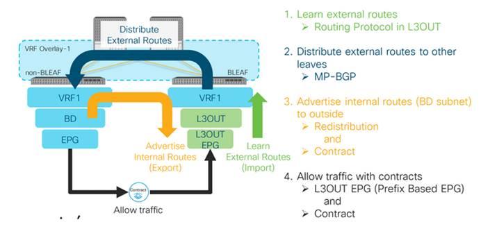
Transit Routing through the ACI Fabric
Transit routing through the ACI fabric
![Cisco Application Centric Infrastructure Fundamentals, Release 4.2(x) - ACI Transit Routing, Route Peering, and EIGRP Support [Cisco Application Policy Infrastructure Controller (APIC)] - Cisco](https://lh7-us.googleusercontent.com/rflVVepOFCtZxr0WElhmGjhebaRsFbEIzpWalnaMv88g6EaHnp1hRzksDbgepB6wMMUQsNZbozsE4VC5_uAN3tVNTp_1LwJgo97Ldx_LjBu4NjWdYzBgBaIKjQaq6XKZpco-q0mAc33pLa6xvm-QtA)
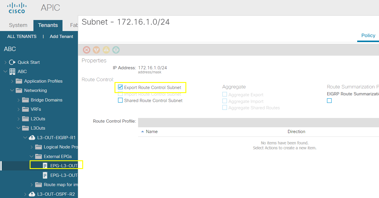
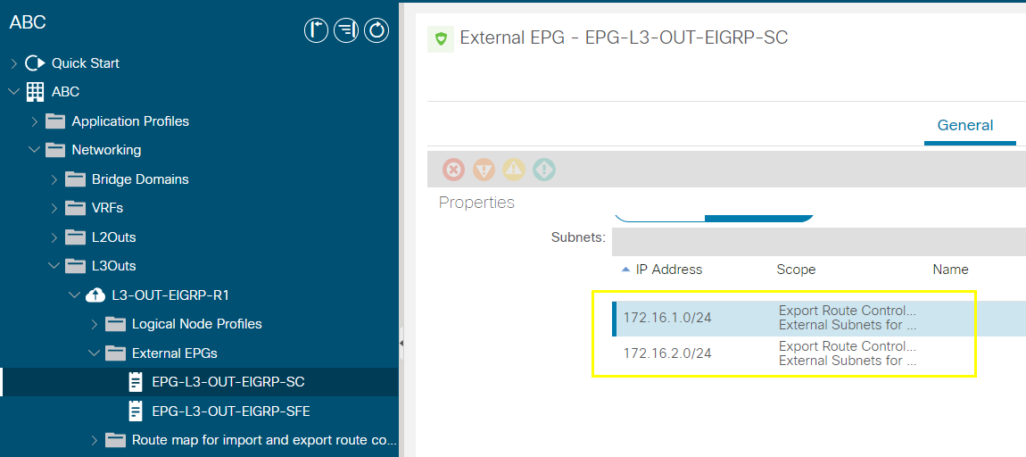
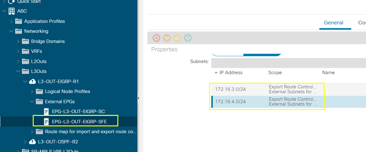
ACI subnet advertised externally means routes will be advertised to L3 OUT router
--------------------------------------------------------------------------------------------------------------------------------------------------------------------------------------
--------------------------------------------------------------------------------------------------------------------------------------------------------------------------------------
External Firewall Integration Overview

Additional Features
Configuring an external firewall Integration
--------------------------------------------------------------------------------------------------------------------------------------------------------------------------------------
--------------------------------------------------------------------------------------------------------------------------------------------------------------------------------------
Configuring Firewall Integration
# Base ACI Configuration
APIC Bootstrap
Fabric discovery process to setup the leafs and spines
Access provisioning
Interface policies
IPGs
Interface profiles : create a common profile same for client and servers
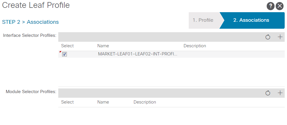
Switch profile: call both the leaf switches in the same switch profile and link to the interface profile
VLAN pools [1-500]
Domains: ACI, L2-OUT and L3-Out
AAEP
3. Tenant provisioning
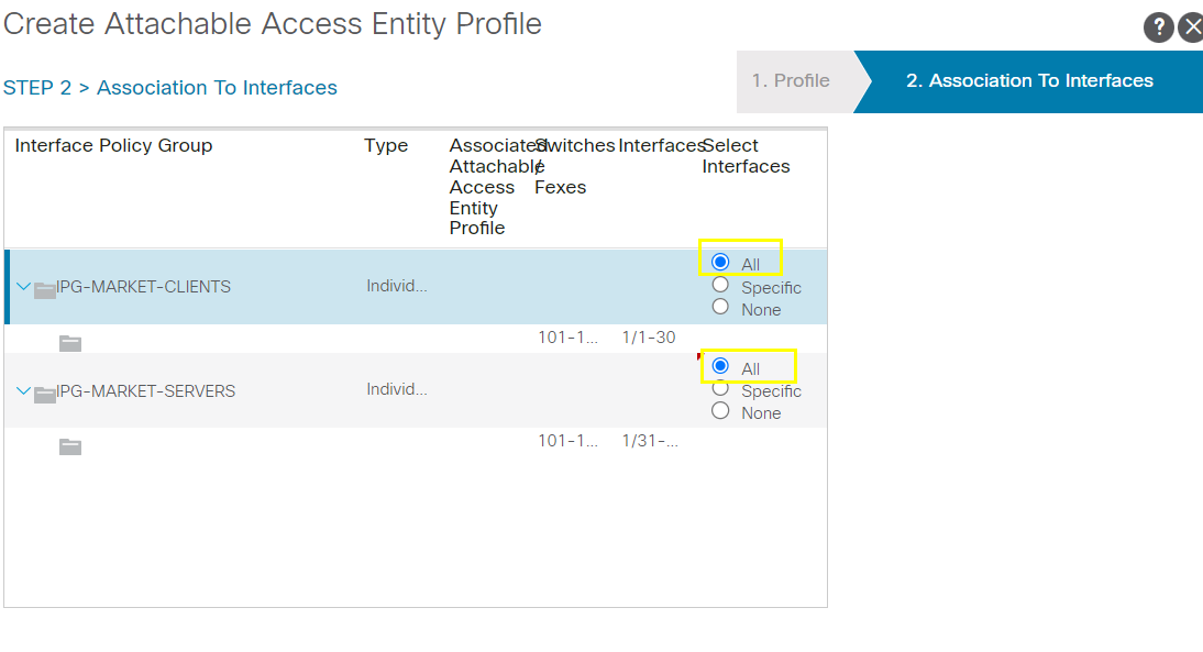
Create IPG-MARKET-CLIENT
Create IPG-MARKET-SERVER
Create Interface profile
Create switch profile
Create AAEP
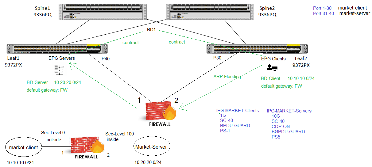
Create separate bridge domain for clients and servers
Create a tenant - ABC
Create a VRF - GRT
Create 2 bridge domains: BD-MARKET-CLIENTS [10.10.10.254/24], BD-MARKET-SERVERS [10.20.20.254/24]
"when creating the DB enable - 'ARP Flooding'
Specify the 2 subnets
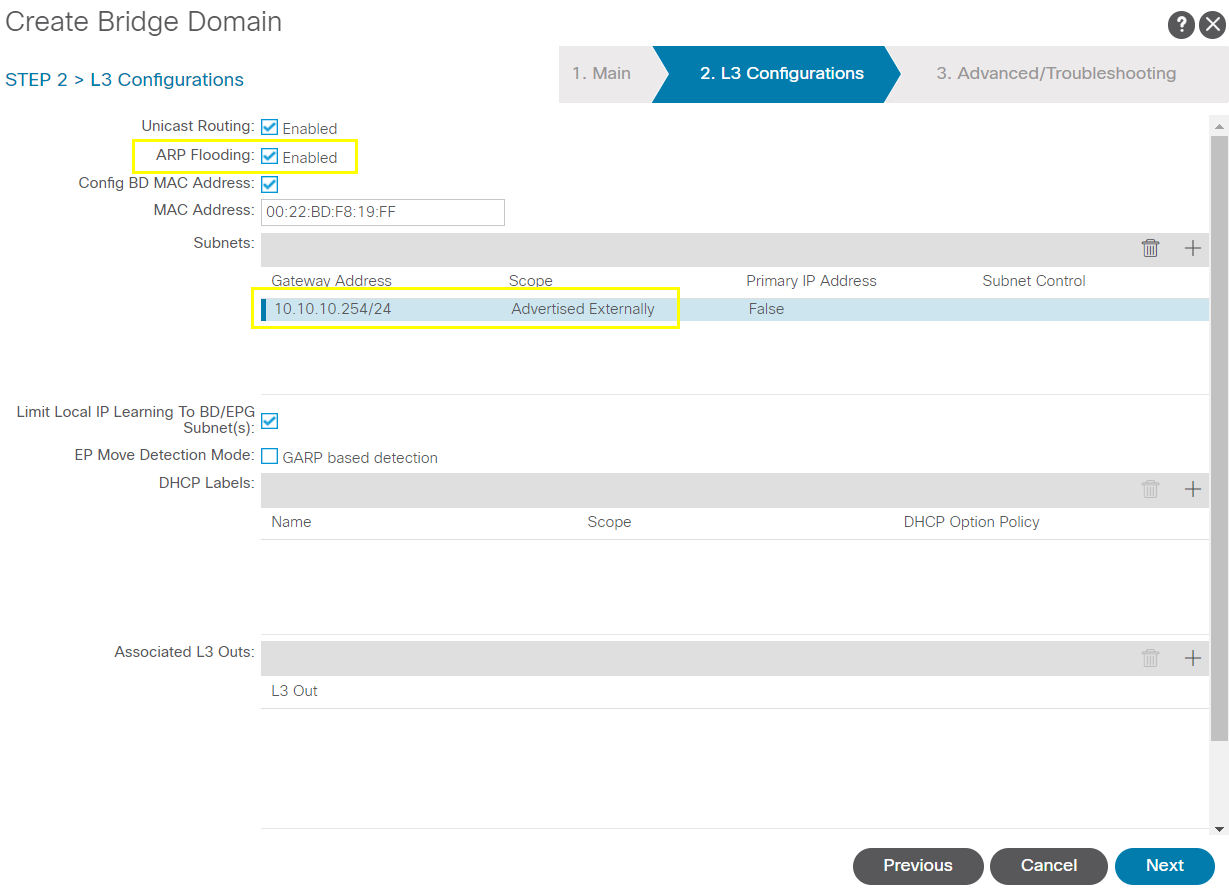
Next/finish

Next/finish
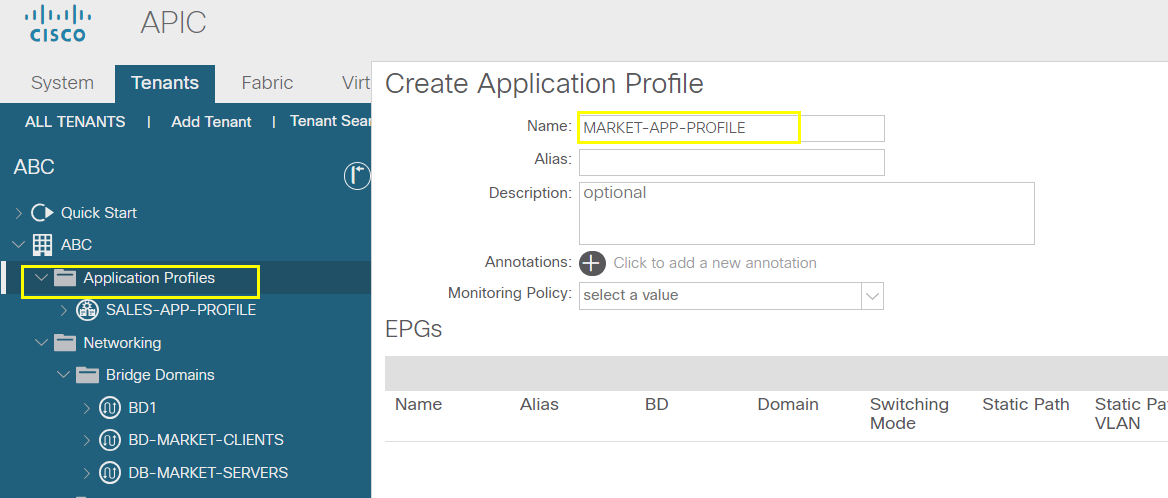
Create the application provisioning
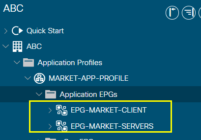
Create the MARKET-APP-PROFILE
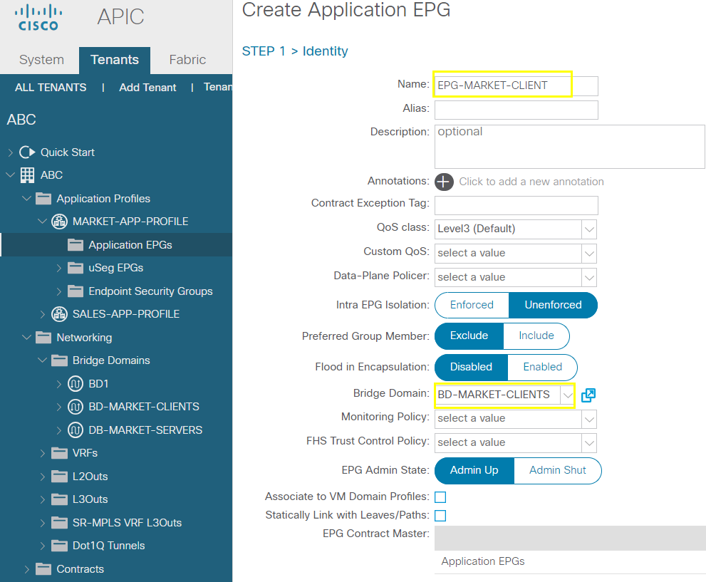
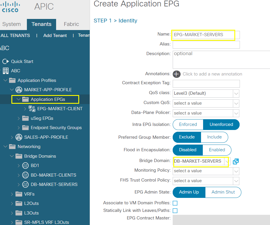
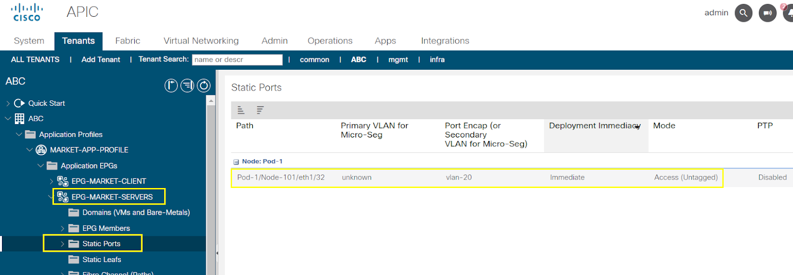
Create 2 EPGs: EPG-MARKET-CLIENT (BD-MARKET-CLIENT) and EPG-MARKET-SERVERS (BD-MARKET-SERVERS)
Static port
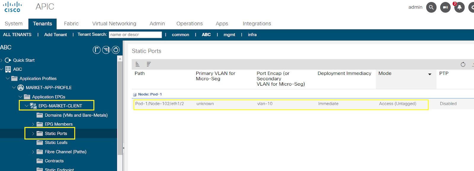
Normally we create contract for the two EPG to talk to each other, but we don't create contract. Will allow firewall to be integrated
Respectively port 40 and port 30
We are not creating contracts in ACI to control the Traffic flow between this 2 BDs or EPGs
We want External Firewall to contract the traffic between the Mark-Clients and Market-servers
--------------------------------------------------------------------------------------------------------------------------------------------------------------------------------------
--------------------------------------------------------------------------------------------------------------------------------------------------------------------------------------
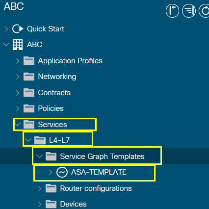
Firewall Services for External Firewall

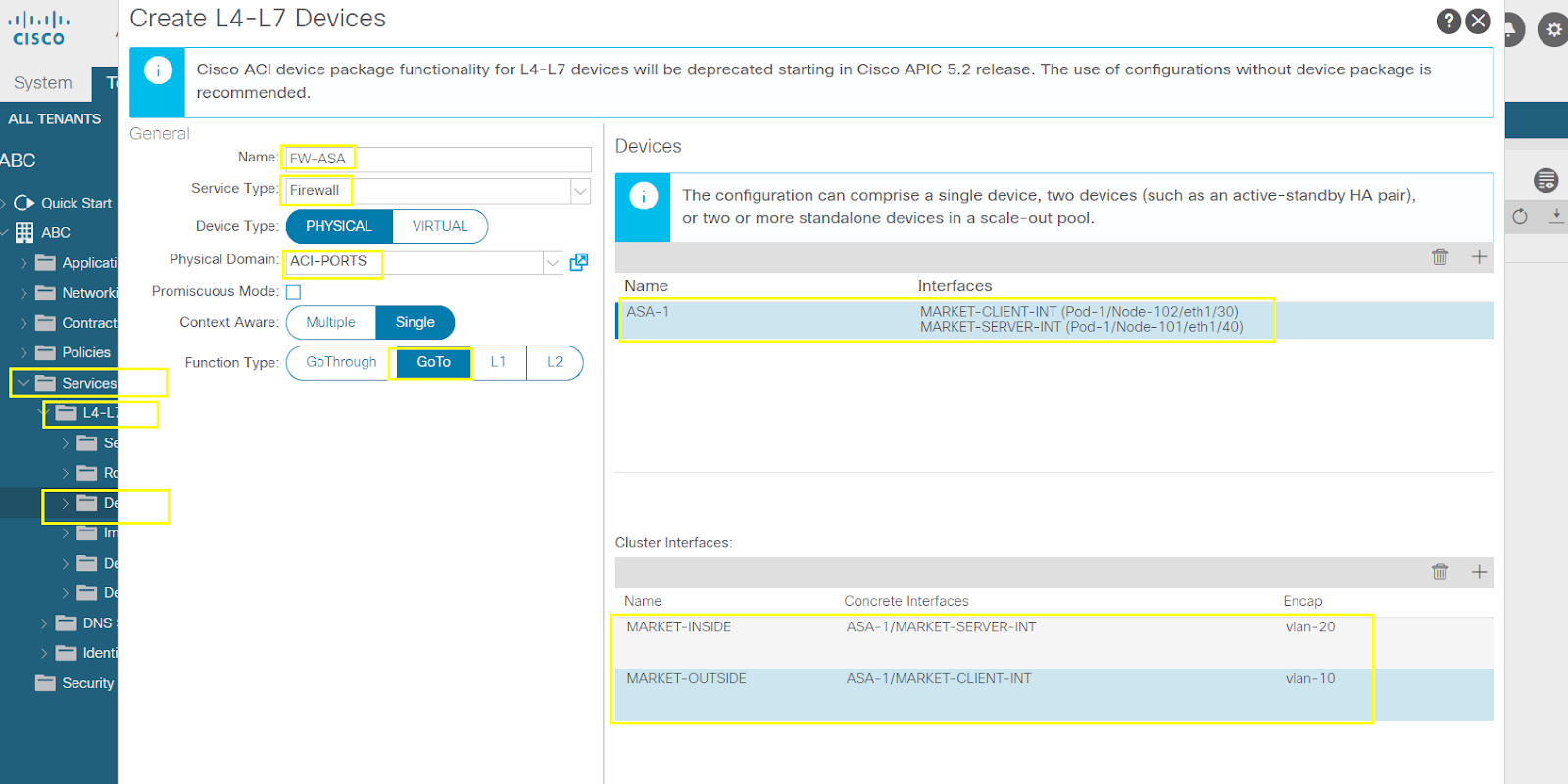
Create a firewall service for the external firewall integration
Create L4-L7 devices
Go through : L2 FW
Go to : L3 FW
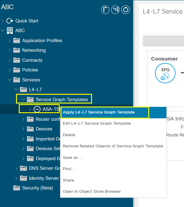
Create a service graph template using the device created
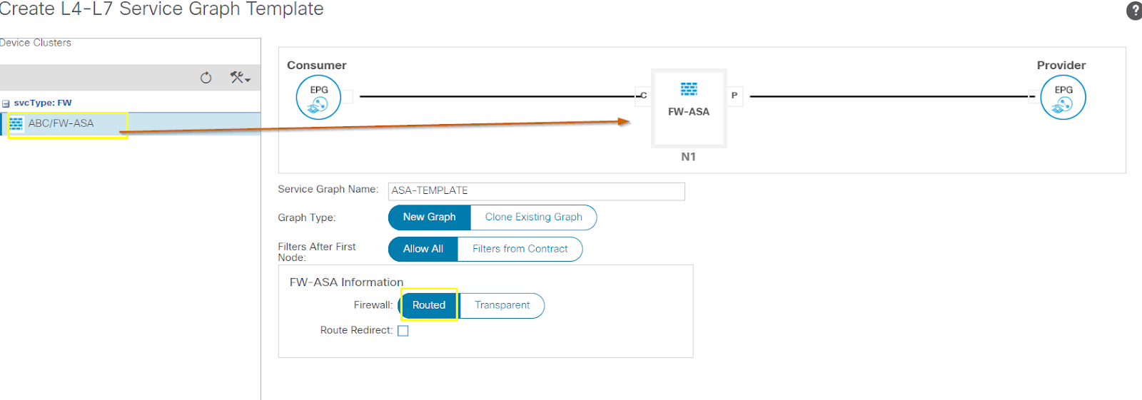

Next
Consumer DB: MARKET-CLIENTS
Cluster Interface: MARKET-OUTSIDE
!
Provider DB : MARKET-SERVER
Cluster Interface: MARKET-INSIDE
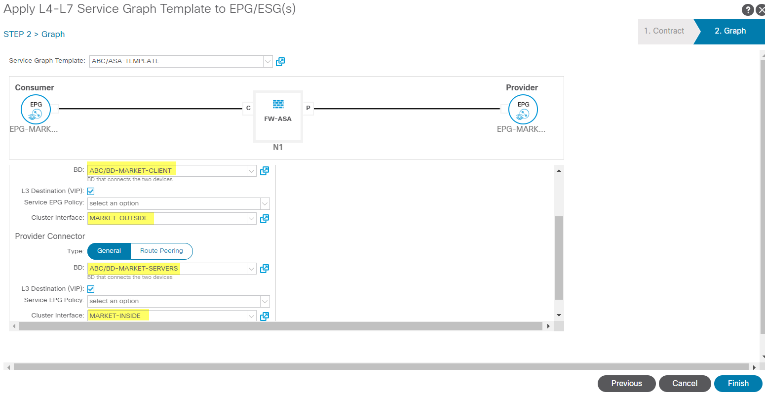
*** Make sure we point the client and servers default gateway to the firewall IPs not the ACI Leaf switch IP addresses
--------------------------------------------------------------------------------------------------------------------------------------------------------------------------------------
--------------------------------------------------------------------------------------------------------------------------------------------------------------------------------------
Single-Pod Single Cluster vs Multi-pod Single Cluster
# ACI Multi-Pod / Multi-site Setup Architectures
Single pod single cluster
Multi pod single cluster
--------------------------------------------------------------------------------------------------------------------------------------------------------------------------------------
--------------------------------------------------------------------------------------------------------------------------------------------------------------------------------------
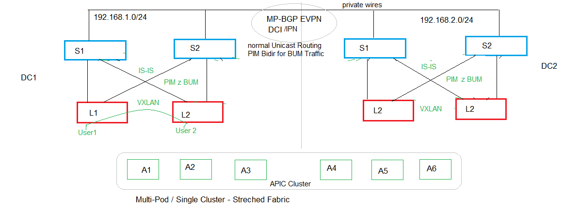
Multi-pod Single Cluster - Stretched Fabric
# ACI Multi-Pod / Multi-site Setup Architectures
Single pod single cluster
- This is the usual setup that we have been doing from day 1 in Single site/DC
- In this architecture, all switches are present or connected within the same DC
- Typical Spine/Leaf architecture managed by Cluster of APICs
- The APICs are in a Spine cluster
- In this setup, Fabric - IS-IS and PIM Control Plane protocols which is used to provide the connectivity between the Leafs via the Spines
- In the fabric, the VXLAN will provide the data plane reachability for the end devices that we attach.
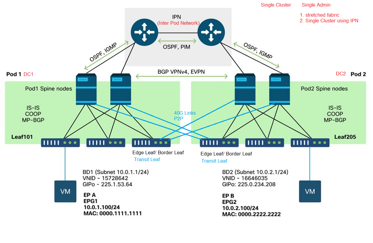
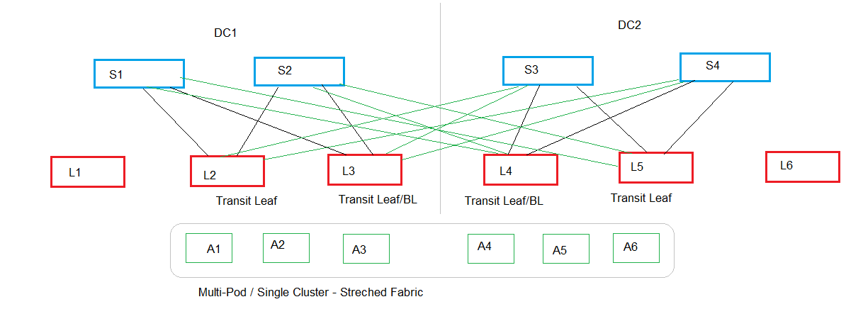
Multi pod /single cluster - Using stretched Fabric
- In this design, we will have multiple site/pods generally located in 2 separate DC
- we connect the Pods using one or more Leafs to the spines in the remote DC.
- Although we have 2 separate DC, they are now going to be treated as a Single Entity from the mgmt plane view.
- All the APICs are in the same cluster. If we create an EPG on Site1/pod 1, it will be replicated to the remote sites.
- Limitations are up to 250 leafs.
- the major drawback of this design is the scalability.
--------------------------------------------------------------------------------------------------------------------------------------------------------------------------------------
--------------------------------------------------------------------------------------------------------------------------------------------------------------------------------------
Single Cluster Using IPN
--------------------------------------------------------------------------------------------------------------------------------------------------------------------------------------
--------------------------------------------------------------------------------------------------------------------------------------------------------------------------------------
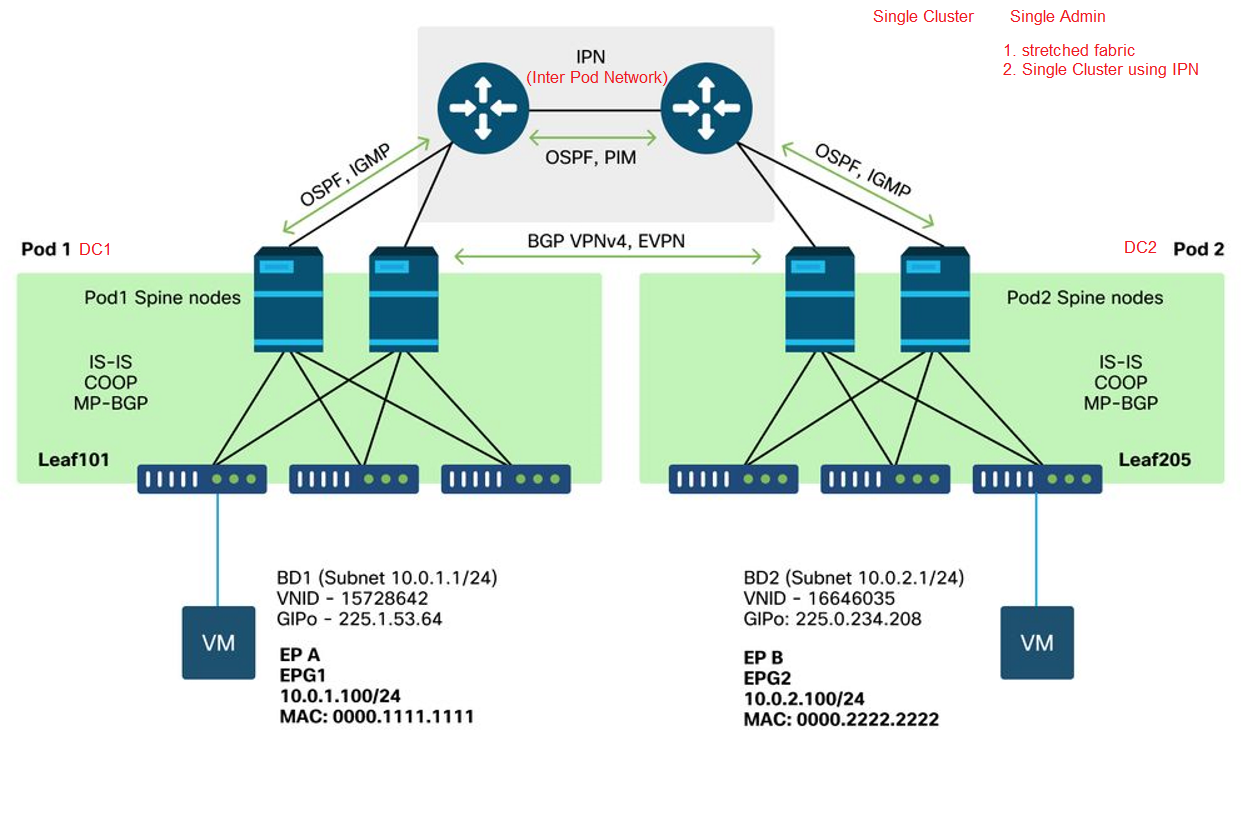
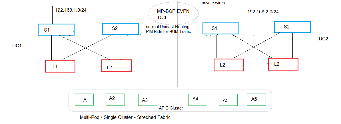
Multi-Pod Single Cluster - Using IPN
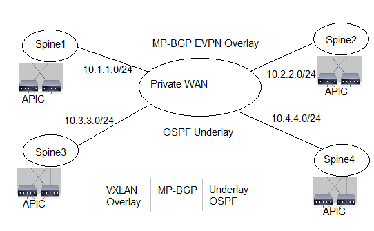
Multi-Pod / Single Cluster - Using L3 IPN
- in this design, we will have multiple Pods connected in 2 or more separate DCs
- we Connect the pods to each other by connecting the spines using a L3 connections to a private WAN
- we run an IGP / static routes to provide the reachability between the Spines on the IPN network
- we need to run PIM-directional for BUM Traffic
- Once the underlay routing will provide reachability between the spines, we use MP-BGP EVPN to provide the overlay service to connect different DC to each other.
- MP-BGP will provide the underlay to connect the data plane between the 2 sites.
- the data plane is the VXLAN
- this is still a single cluster design.
So far we have discussed:
1. Single Pod: Single Cluster
2. Multi-Pod: Single Cluster --> Transit Leaf Connection AKA Stretched Fabric
3. Multi-Pod: Single Cluster --> Spine to spine connection using the L3 IPN
--------------------------------------------------------------------------------------------------------------------------------------------------------------------------------------
--------------------------------------------------------------------------------------------------------------------------------------------------------------------------------------
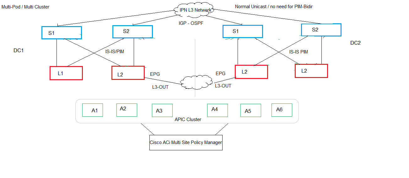
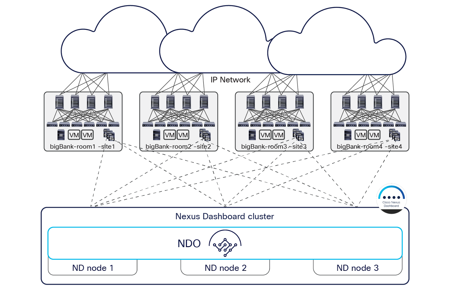
Multi-Pod Multi cluster
Cisco ACI Multi-Site Architecture White Paper
Multiple Clusters
Using a normal L3-OUT on the leaf using any L3 network as an IGP/EGP to connect other site
Easiest method
We use the normal EPGs and contract to connect
The EPGs are created based on the external IP network
We are using the leafs to connect multiple DCs to each other.
Using an IPN network to connect the spines to provide the inter-pod communication
Similar setup like Multi-pod single cluster using the spines
We need to configure an IGP like OSPF to provide the spine to spine connectivity
We will configure MP-BGP EVPN to exchange the Fabric information with the other Pod like the Leaf Ip address etc.
Unlike the Multipod/single cluster, the IPN does not need the PIM-Bidirectional configurations.
As they are two separate clusters
We can leverage the use of Cisco ACI multisite policy manager (Nexus dashboard cluster) to manage and configure the APICs of the two domains