Oracle Session Monitoring Installation
– Probe to Mediation Engine Connection (Version 4.1.0.3.0)
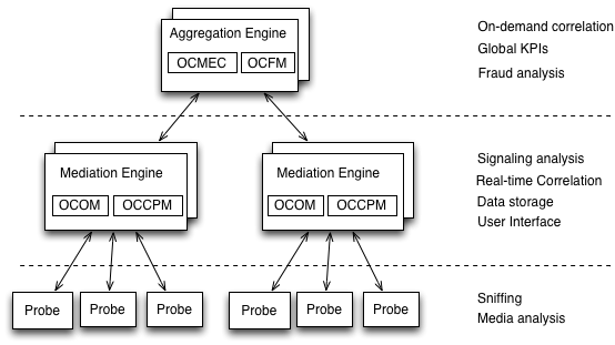
The Operations Monitor Probe can connect to one or more Mediation Engines, using TLS encryption,
or with some configurations, also cleartext. Likewise, a Mediation Engine can connect to more than one Operations Monitor Probe (as well as Session Border Controller Probes).
or with some configurations, also cleartext. Likewise, a Mediation Engine can connect to more than one Operations Monitor Probe (as well as Session Border Controller Probes).
The probes send meta-data for each of the signaling messages to the Mediation Engine layer and analyze
the RTP streams locally, sending the results of this analysis to the Mediation Engine layer.
the RTP streams locally, sending the results of this analysis to the Mediation Engine layer.
Figure 1-1 Session Monitor System Architecture
Oracle Linux : 7.5 (V975367-01.iso)
Session Monitor RPM file: p29473233_41000_Acme_Packet.zip
Enterprise edition of MySQL in version 5.7.10: p22322140_570_Linux-x86-64_mysql5.7.10.zip
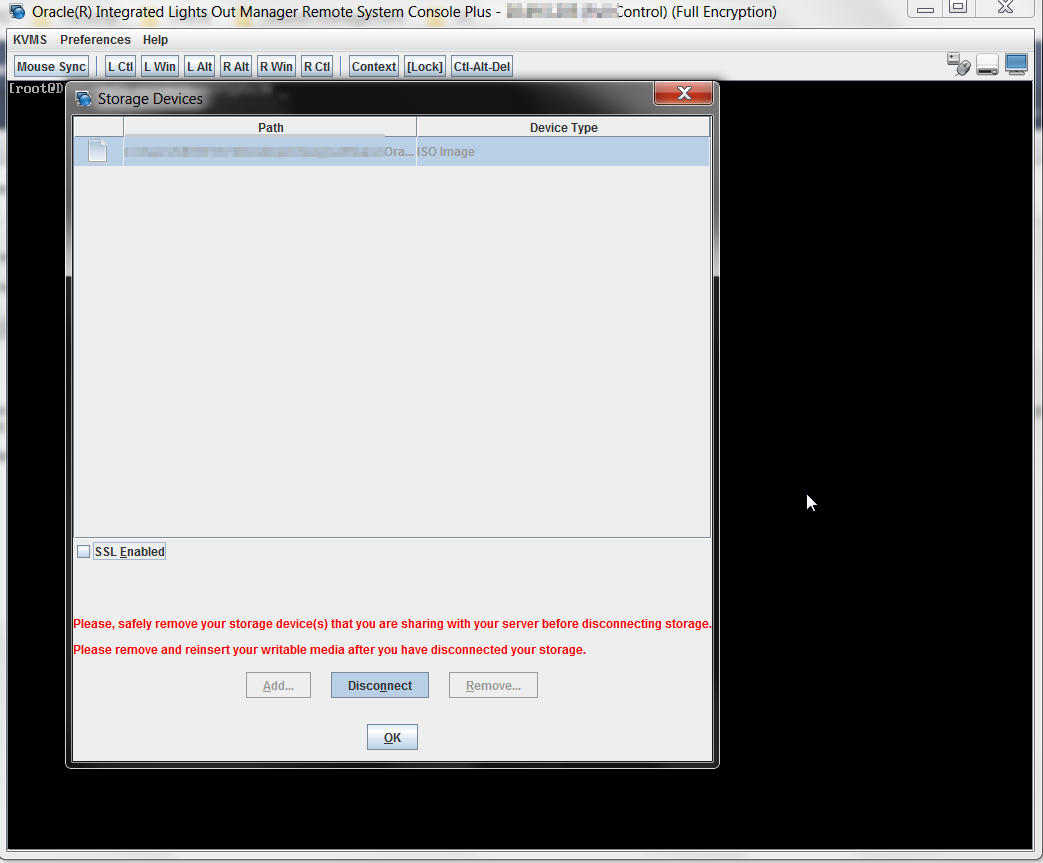
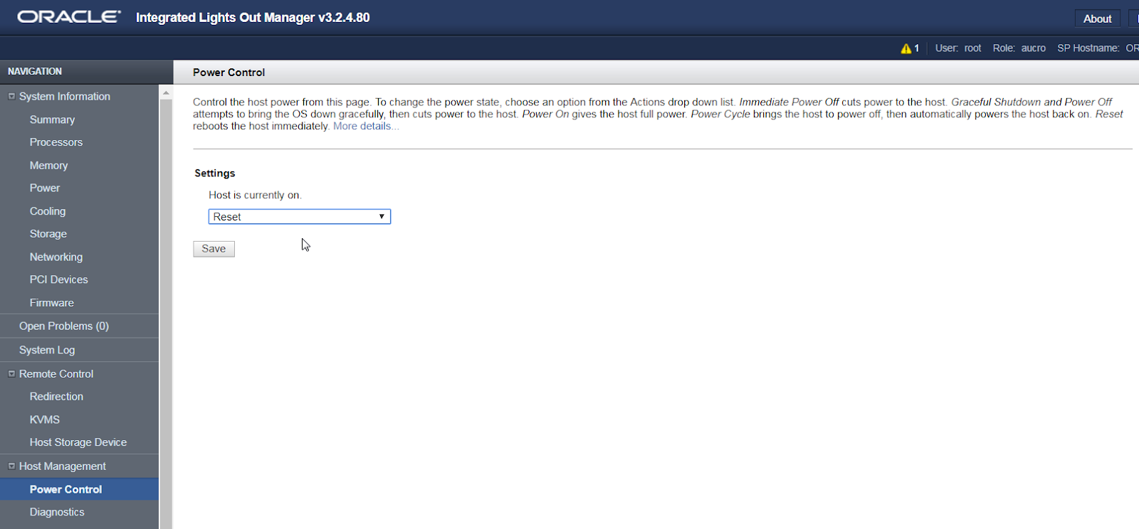
Login to iLom and lunch Remote Console

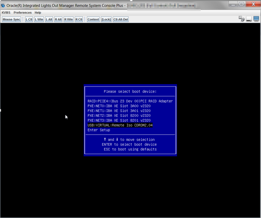
Mount Linux 7.5
Reboot
Boot from Remote ISO
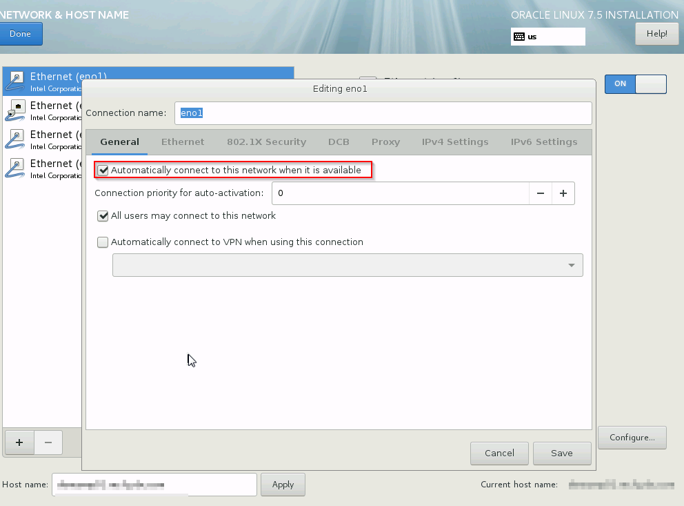
Configure IP address and tick automatic connect
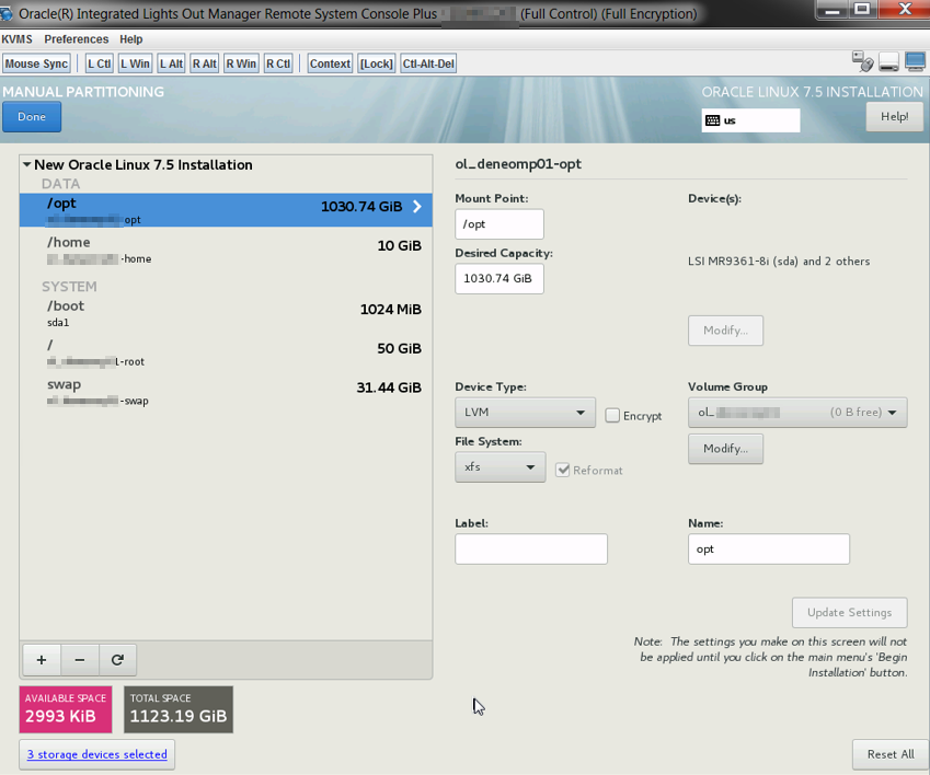
Make reasonable partition
Conigure Yum.conf proxy (optional)
proxy=http://HTTP_PROXY:PORT
proxy_username=USERNAME
proxy_password=PASSWORD
sslverify=false
Export http proxy variable(optional)
export http_proxy=http://USERNMAE:PASSWORD@PROXY_HOST:PORT
export https_proxy=$http_proxy
Download latest Repo file
mv public-yum-ol7.repo /etc/yum.repos.d/public-yum-ol7.repo
yum install -y yum-utils
yum-config-manager --enable ol7_latest ol7_UEKR4 ol7_developer_EPEL ol7_optional_latest ol7_addons ol7_UEKR3 ol7_UEKR5
Install latest Enterprise edition of MySQL in version 5.7.10 .
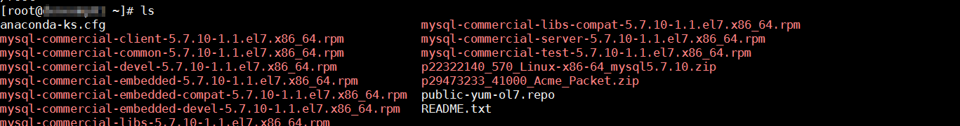
yum install -y mysql-commercial*.rpm
yum-config-manager --enable ol7_latest ol7_UEKR4 ol7_developer_EPEL ol7_optional_latest ol7_addons ol7_UEKR3 ol7_UEKR5
Install the Session Monitor RPM file
yum install ocsm-4.1.0.3.0.x86_64.rpm
Find installation logs
[root@HOSTNAME]# pwd
/var/log/ocsm
[root@HOSTNAMEocsm]# ls
ocsm_installed_XXXXDATE_MDT.log ocsm_preinstall_XXXXXDATE_MDT.log
Turning VSI to handle the additional traffic
Added the following to the file /opt/oracle/ocsm/etc/iptego/vsi.local.conf:
[ip]
table_bits = 16 # default is 10
expires = 30
[storage]
parallel_blocks=20
prealloc_blocks=40
startup_blocks=8
[users]
xmlrpc_search_minimum_results=0
xmlrpc_search_timeout=2
table_bits=24
[tm]
table_bits = 24
Added the following to the file /opt/oracle/ocsm/etc/iptego/vsi.local.conf:
[ip]
table_bits = 16 # default is 10
expires = 30
[storage]
parallel_blocks=20
prealloc_blocks=40
startup_blocks=8
[users]
xmlrpc_search_minimum_results=0
xmlrpc_search_timeout=2
table_bits=24
[tm]
table_bits = 24
Adjust the firewall
firewall-cmd --permanent --zone=public --add-service=https
firewall-cmd --permanent --zone=public --add-port=4739/tcp
firewall-cmd --permanent --zone=public --add-port=4740/tcp
firewall-cmd --permanent --zone=public --add-port=4741/tcp
firewall-cmd --permanent --zone=public --add-port=4742/tcp
firewall-cmd –reload
login to Session Monitor
username: sysadmin
password: oracle
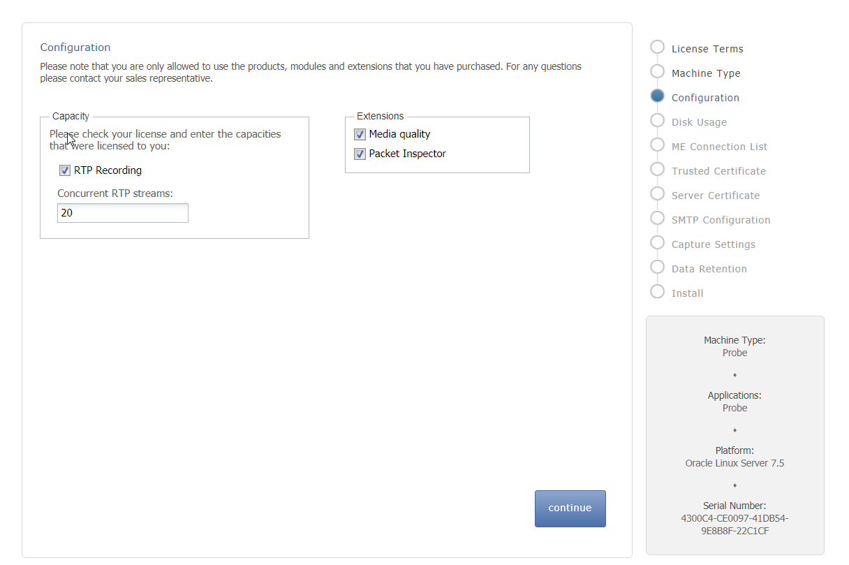
Configure Platform Setup Application
Choose Probe as Machine type

Add new ME connection

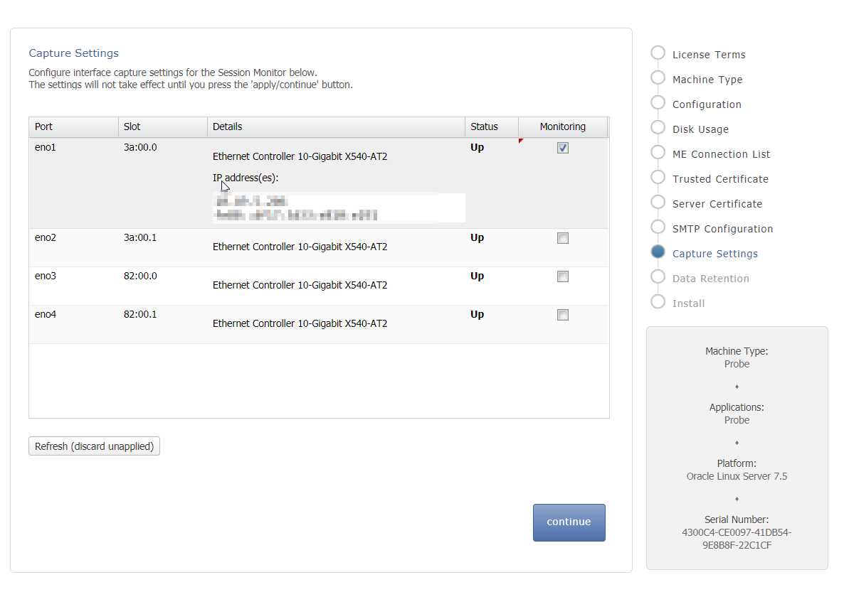
Enable capture
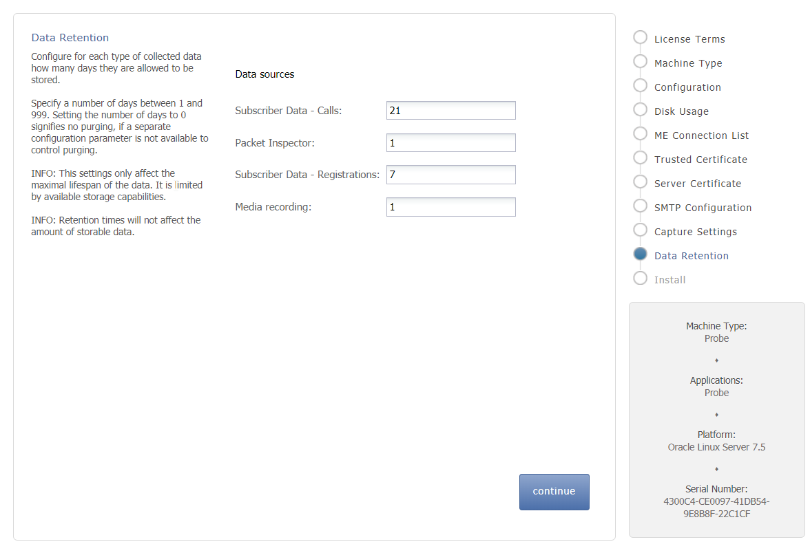
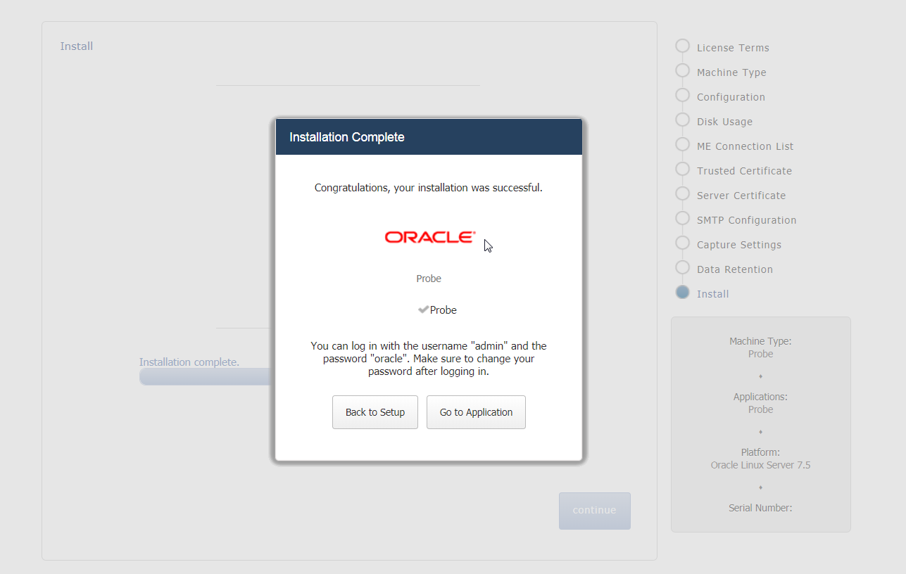
Install
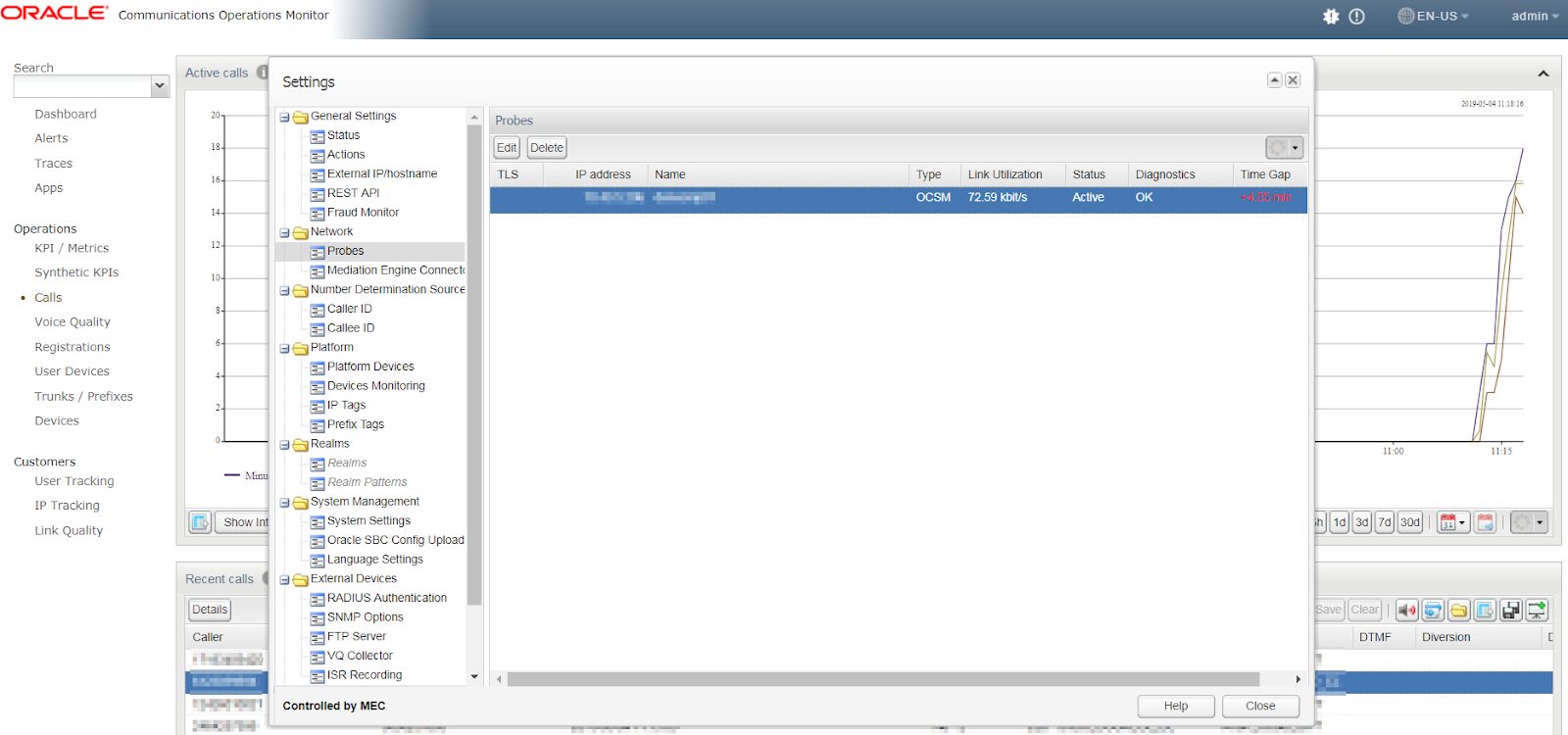
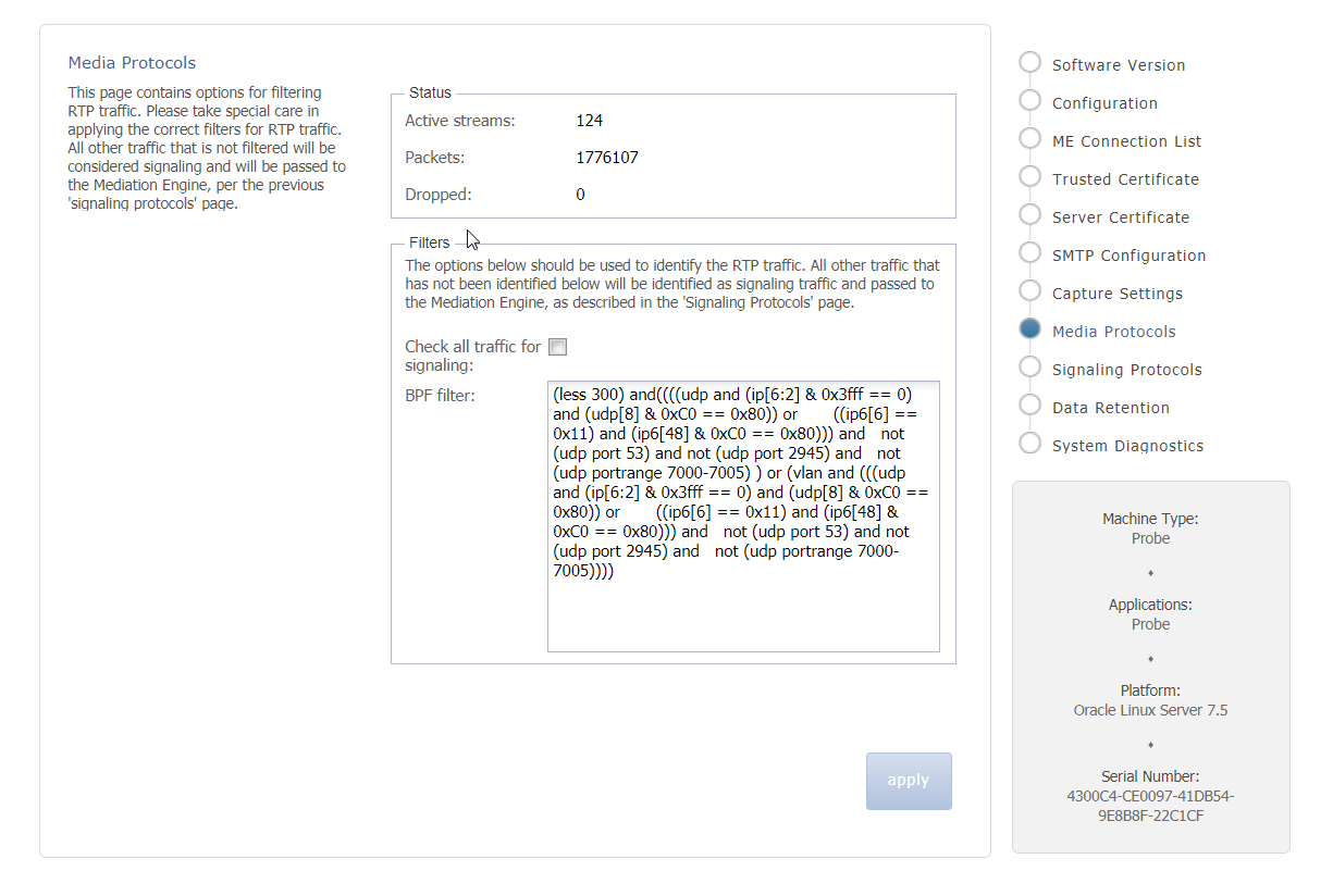
Check packets are growing
Login to ME node and see Probes detected automatically