DCACI - ACI
Create Access Policies and vPC
Enable Layer 2 Connectivity in the Same EPG
Enable Inter-EPG Layer2 Connectivity
Configuring Out-of-Band Management
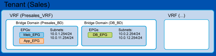
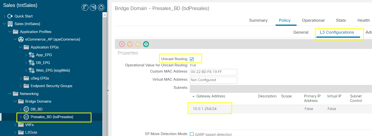
Configure Bridge Domain DB_BD with Subnet and EPG with
Configure External Layer 3 (L3Out) Connection
--------------------------------------------------------------------------------------------------------------------------------------------------------------------------------------
--------------------------------------------------------------------------------------------------------------------------------------------------------------------------------------
Core Knowledge
Cisco Nexus 9500 Series modular chassis
4-slot, 8-slot, and 16-slot
Support 10GE, 40GE, 100GE, and 400GE modules
Cisco Nexus 9300 Series top-of-rack (ToR) leaf and spine switches
Cisco ACI spine and leaf varieties
1/10/40/100/400 GE interface speeds
Cisco Nexus 9300 ACI Fixed Spine Switches
Several Cisco Nexus 9300 models can be deployed as Cisco ACI spine switches:
Cisco Nexus 9364C (64x 100/40GE)
Cisco Nexus 9332C (32x 100/40GE)
Cisco Nexus 9336PQ (36x 40GE)
Cisco Nexus 9316D-GX (16x 400GE)
Cisco Nexus 9300 ACI Fixed Leaf Switches
Cisco ACI leaf spectrum includes:
40/100-GE switch examples:
Cisco Nexus 9336C-FX2 (36x 40/100GE)
Cisco Nexus 93180LC-EX (24x 40/50GE, 6x 40/100GE)
Cisco Nexus 9332PQ (32x 40GE)
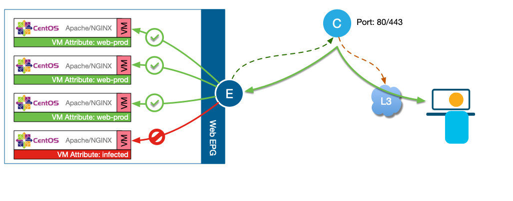
Intra-EPG isolation
Intra-EPG Isolation is an option to prevent physical or virtual endpoint devices that are in the same base EPG or microsegmented (uSeg) EPG from communicating with each other. By default, endpoint devices included in the same EPG are allowed to communicate with one another. However, conditions exist in which total isolation of the endpoint devices from on another within an EPG is desirable. For example, you may want to enforce intra-EPG isolation if the endpoint VMs in the same EPG belong to multiple tenants, or to prevent the possible spread of a virus
--------------------------------------------------------------------------------------------------------------------------------------------------------------------------------------
--------------------------------------------------------------------------------------------------------------------------------------------------------------------------------------
Validate Fabric Discovery
The AV on each node (both switches and APICs) can be checked via acidiag avread command:
apic1# acidiag avread
Local appliance ID=1 ADDRESS=10.0.0.1 TEP ADDRESS=10.0.0.0/16 ROUTABLE IP ADDRESS=0.0.0.0 CHASSIS_ID=10220833-ea00-3bb3-93b2-ef1e7e645889
Cluster of 1 lm(t):1(zeroTime) appliances (out of targeted 3 lm(t):1(2024-05-07T14:31:32.934+00:00)) with FABRIC_DOMAIN name=ACI Fabric1 set to version=5.2(1g) lm(t):1(2024-05-07T14:32:39.519+00:00); discoveryMode=PERMISSIVE lm(t):0(zeroTime); drrMode=OFF lm(t):0(zeroTime); kafkaMode=OFF lm(t):0(zeroTime)
appliance id=1 address=10.0.0.1 lm(t):1(2024-05-07T14:30:02.305+00:00) tep address=10.0.0.0/16 lm(t):1(2024-05-07T14:30:02.305+00:00) routable address=0.0.0.0 lm(t):1(zeroTime) oob address=10.61.88.208/27 lm(t):1(2024-05-07T14:30:11.609+00:00) version=5.2(1g) lm(t):1(2024-05-07T14:30:11.862+00:00) chassisId=10220833-ea00-3bb3-93b2-ef1e7e645889 lm(t):1(2024-05-07T14:30:11.862+00:00) capabilities=0X7EEFFFFFFFFF--0X2020--0X1 lm(t):1(2024-05-07T14:36:52.684+00:00) rK=(stable,present,0X206173722D687373) lm(t):1(2024-05-07T14:30:11.614+00:00) aK=(stable,present,0X206173722D687373) lm(t):1(2024-05-07T14:30:11.614+00:00) oobrK=(stable,present,0X206173722D687373) lm(t):1(2024-05-07T14:30:11.614+00:00) oobaK=(stable,present,0X206173722D687373) lm(t):1(2024-05-07T14:30:11.614+00:00) cntrlSbst=(APPROVED, TEP-1-1) lm(t):1(2024-05-07T14:30:11.862+00:00) (targetMbSn= lm(t):0(zeroTime), failoverStatus=0 lm(t):0(zeroTime)) podId=1 lm(t):1(2024-05-07T14:30:02.305+00:00) commissioned=YES lm(t):1(zeroTime) registered=YES lm(t):1(2024-05-07T14:30:02.305+00:00) standby=NO lm(t):1(2024-05-07T14:30:02.305+00:00) DRR=NO lm(t):0(zeroTime) apicX=NO lm(t):1(2024-05-07T14:30:02.305+00:00) virtual=NO lm(t):1(2024-05-07T14:30:02.305+00:00) active=YES(2024-05-07T14:30:02.305+00:00) health=(applnc:255 lm(t):1(2024-05-07T14:30:30.111+00:00) svc's)
---------------------------------------------
clusterTime=<diff=0 common=2024-05-31T18:40:03.221+00:00 local=2024-05-31T18:40:03.221+00:00 pF=<displForm=1 offsSt=0 offsVlu=0 lm(t):1(2024-05-16T21:16:50.268+00:00)>>
---------------------------------------------
You could wipe the cisco APIC using the following commands:
apic1# acidiag touch setup
This command will reset the device configuration, Proceed? [y/N] y
apic1# acidiag reboot
This command will restart this device, Proceed? [y/N] y
Verify the software versions on the fabric switches:
apic1# show firmware upgrade status
Pod Node Current-Firmware Target-Firmware Status Upgrade-Progress(%) Download-Status Download-Progress(%)
---------- ---------- -------------------- -------------------- ------------------------- -------------------- ------------------------- --------------------
1 1 apic-5.2(1g) success 100 - -
1 101 simsw-5.2(1g) not scheduled 0 not-queued 0
1 102 simsw-5.2(1g) not scheduled 0 not-queued 0
1 201 simsw-5.2(1g) not scheduled 0 not-queued 0
1 202 simsw-5.2(1g) not scheduled 0 not-queued 0
apic1#
View TEP IP addresses assigned to the switches over DHCP trhough the Infra VLAN:
apic1# acidiag fnvread
ID Pod ID Name Serial Number IP Address Role State LastUpdMsgId
--------------------------------------------------------------------------------------------------------------
101 1 Leaf-01 TEP-1-101 10.0.96.64/32 leaf active 0
102 1 Leaf-02 TEP-1-102 10.0.96.67/32 leaf active 0
201 1 Spine-01 TEP-1-103 10.0.96.65/32 spine active 0
202 1 Spine-02 TEP-1-104 10.0.96.66/32 spine active 0
Total 4 nodes
Tenant
1 Common: Provides global services to other tenants (NTP, SSH, SNMP..)
2 Infra: used for internal fabric communications ( tunnel/policies: sw-sw, sw-apic)
3 Mgmt: provides access policies for fabric nodes
4 Users: Defined by admin according to the needs
--------------------------------------------------------------------------------------------------------------------------------------------------------------------------------------
--------------------------------------------------------------------------------------------------------------------------------------------------------------------------------------
Configure NTP
Configure NTP server
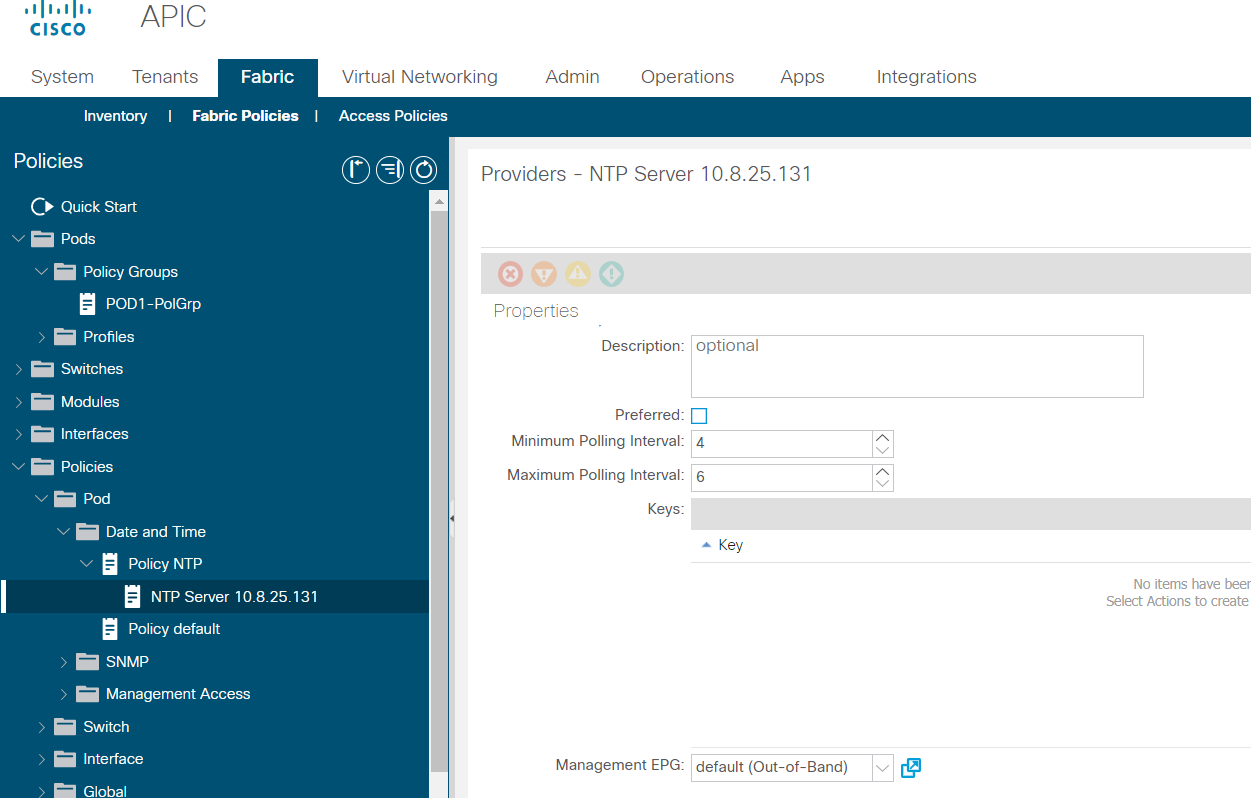
Configure OOB mgmt address

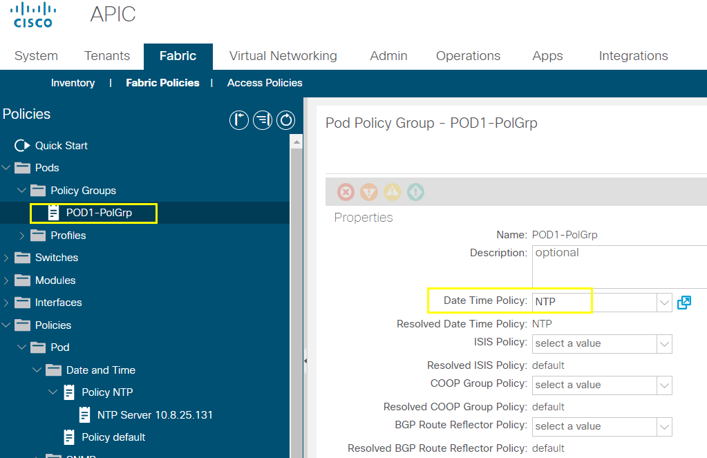
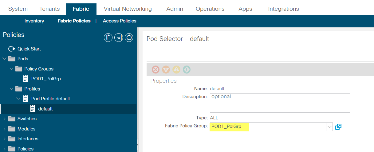
Create policy group and select date and time policy "NTP"
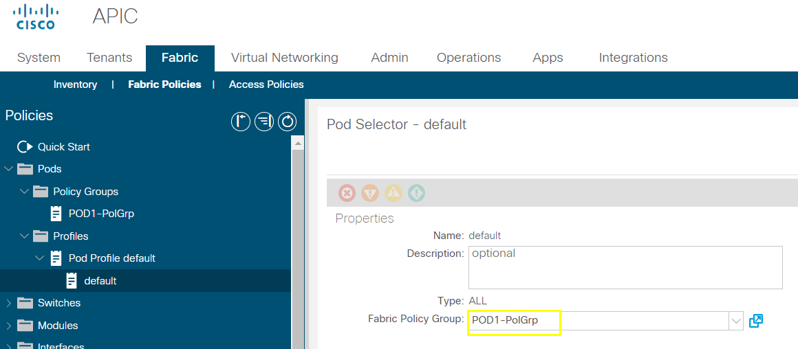
Select default pod profile and select pod policy created
apic1# ntpstat
--------------------------------------------------------------------------------------------------------------------------------------------------------------------------------------
--------------------------------------------------------------------------------------------------------------------------------------------------------------------------------------
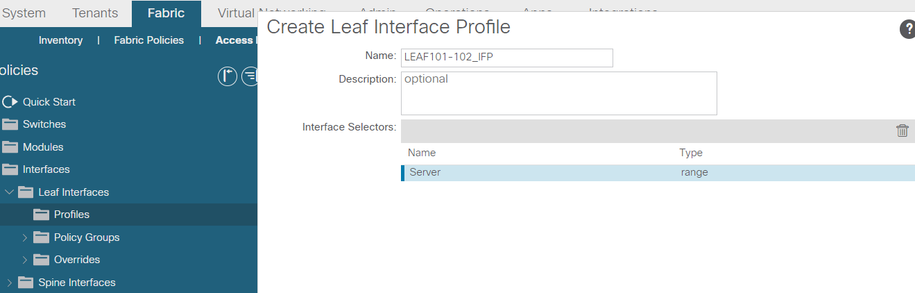
Create Access Policies and vPC
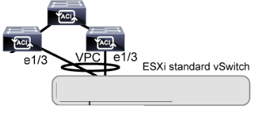
Create Interface profile

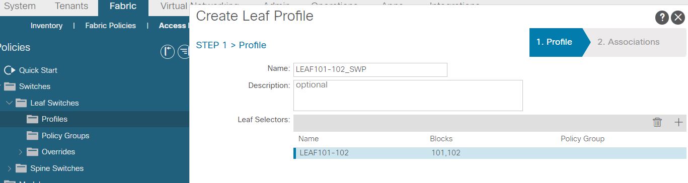
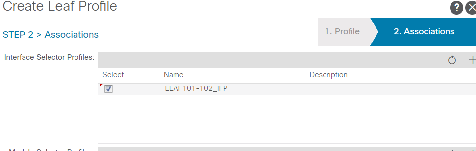
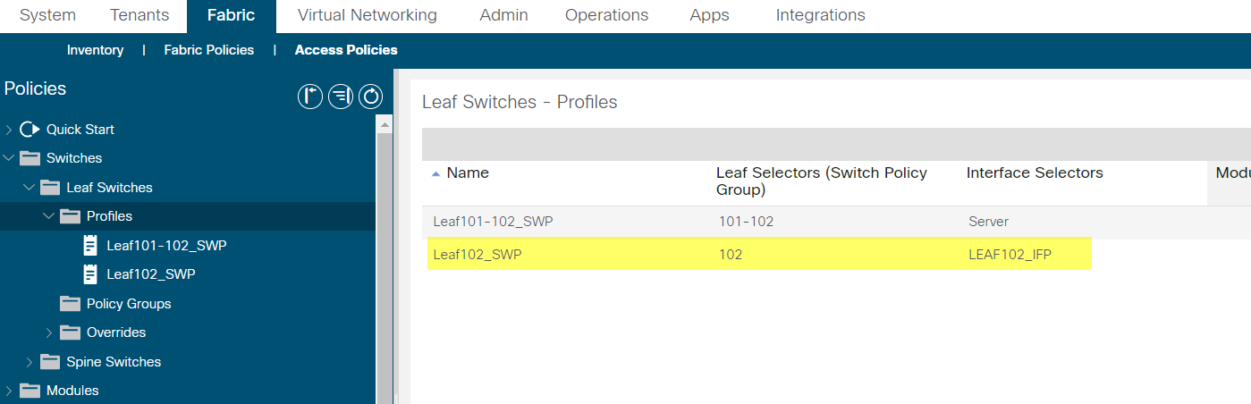
Create Leaf switch profile
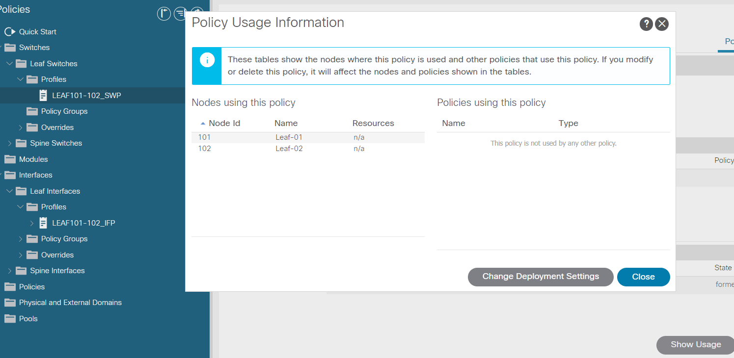
Examining node in use
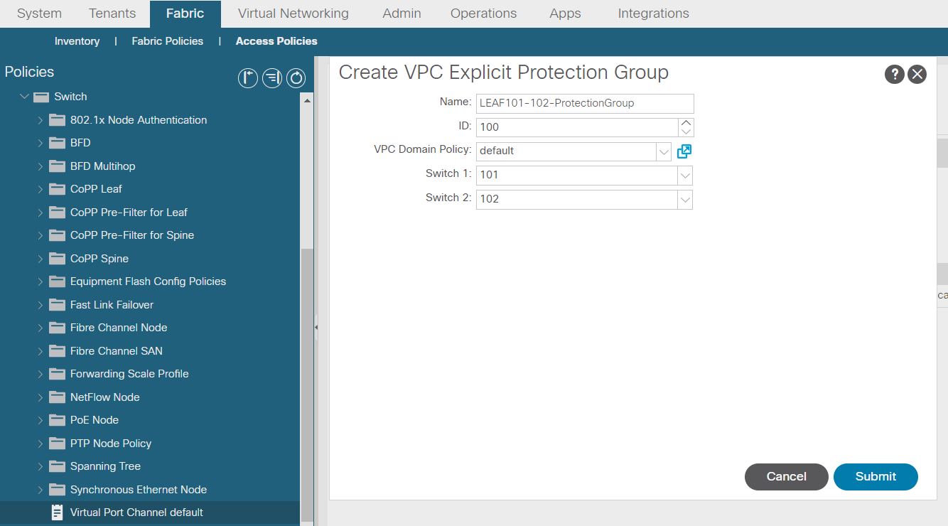
Create VPC security policy
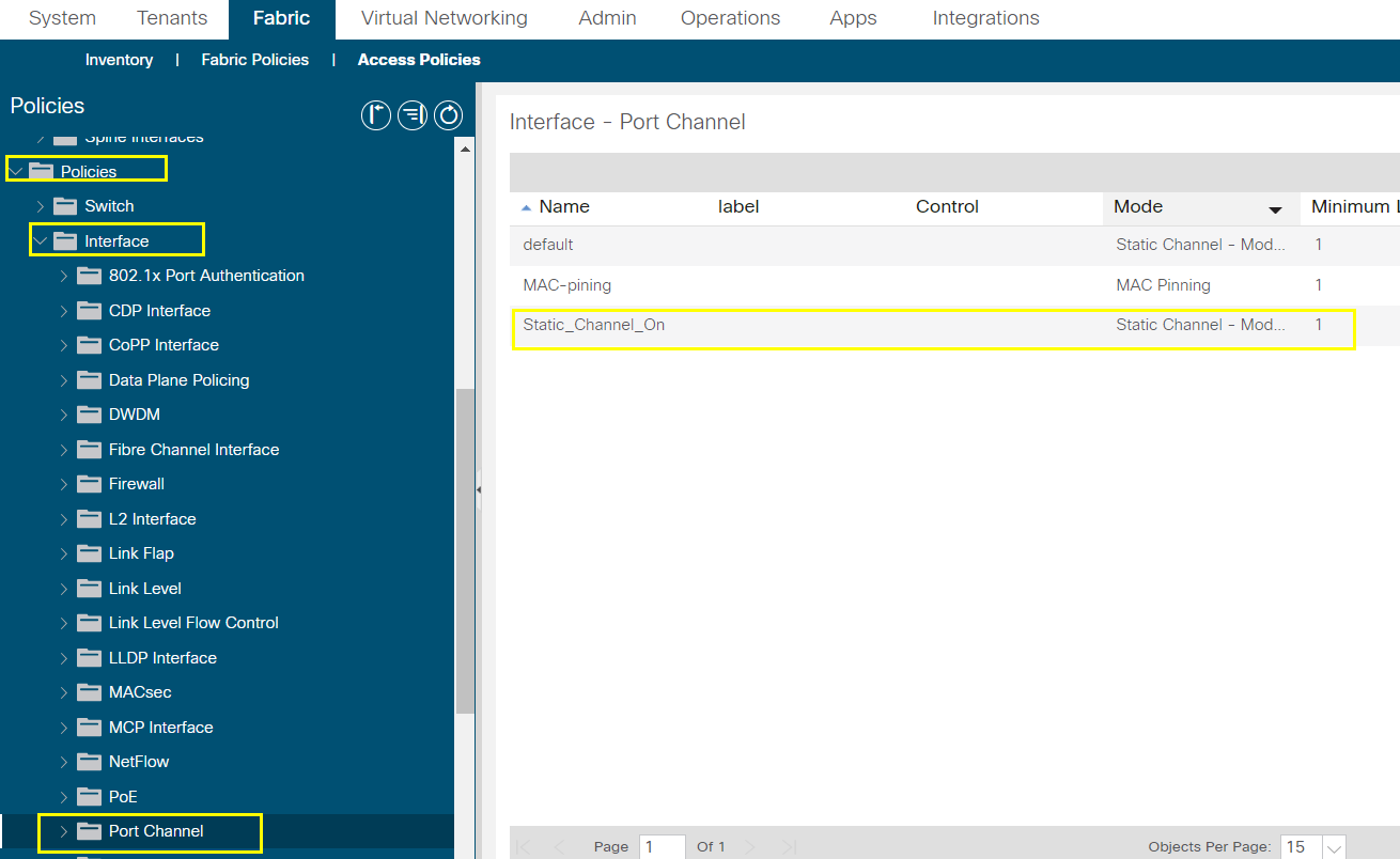
Create interface policy
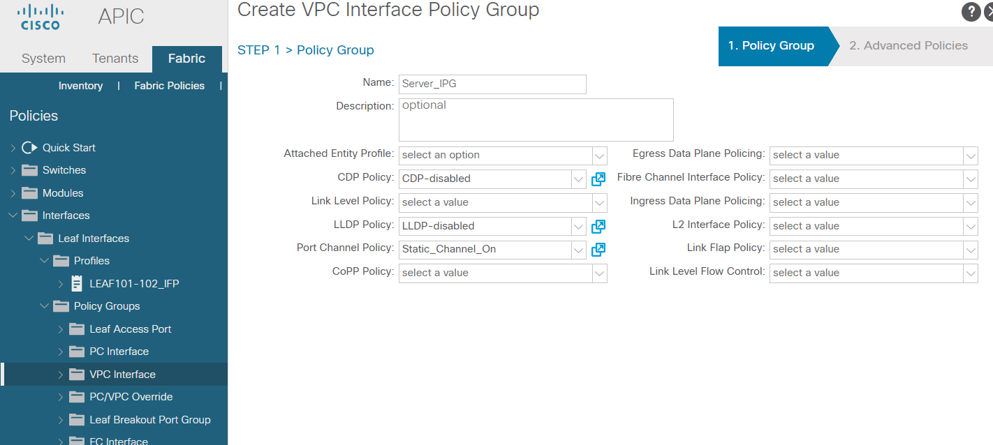
Create VPC IPG
Assign IPG to interface profile
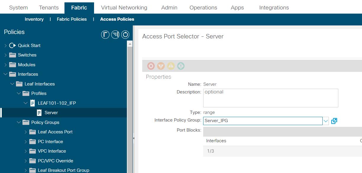
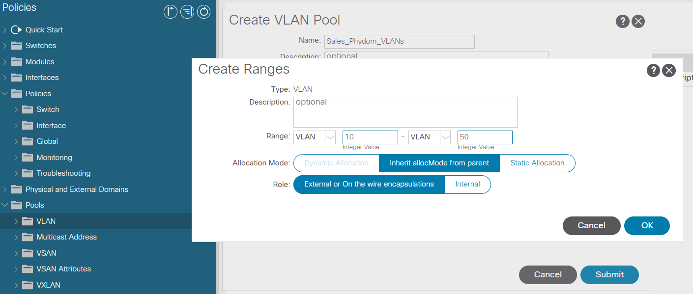
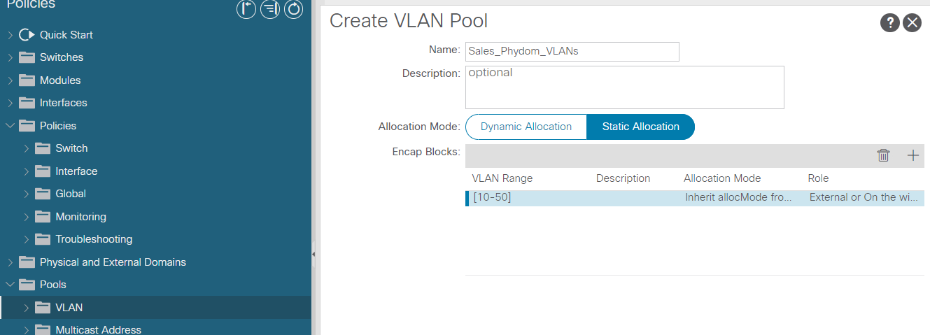
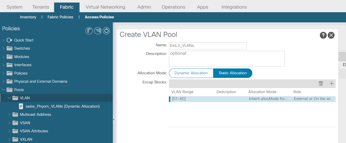
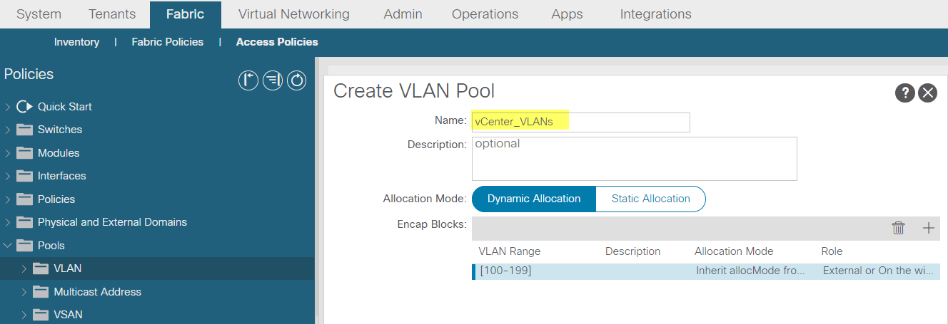
Create vlan pool
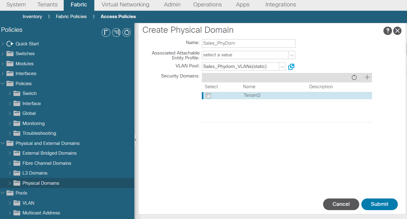
Create physical domain
Create AAEP
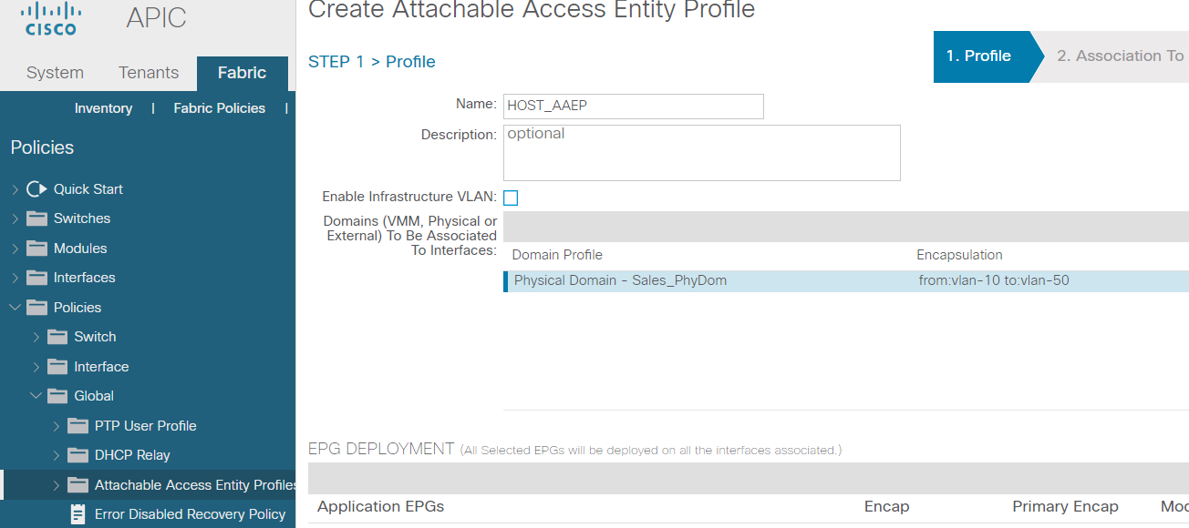
Next and finish
Attach AAEP to IPG

Show vpc
Show vpc role
Show port-channel extended
Show interface port-channel xx
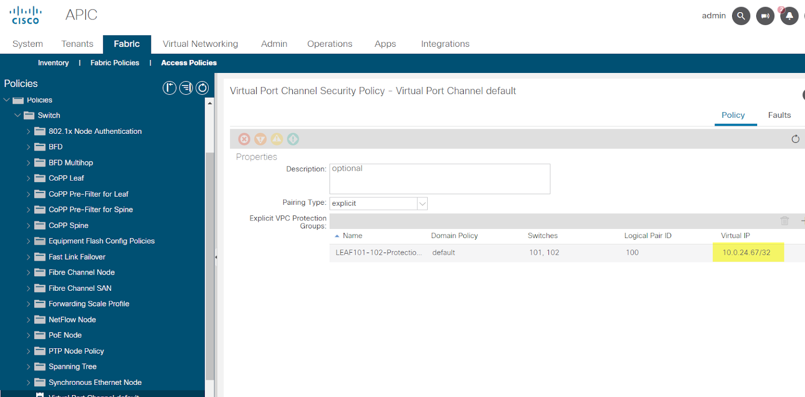
View the vPC TEP address, shown as the virtual IP of the vPC protection group
--------------------------------------------------------------------------------------------------------------------------------------------------------------------------------------
--------------------------------------------------------------------------------------------------------------------------------------------------------------------------------------
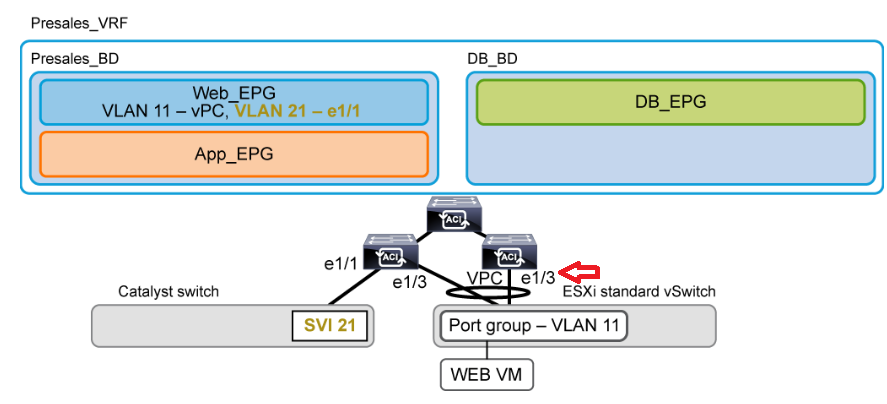
Enable Layer 2 Connectivity in the Same EPG
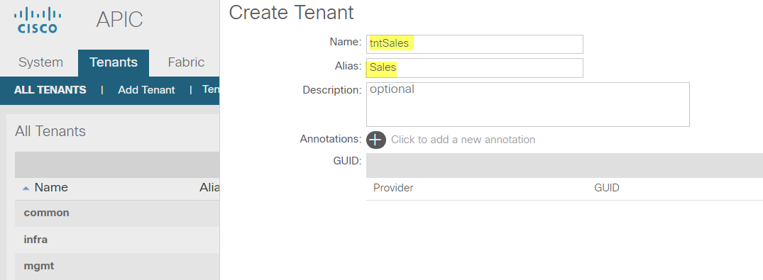
Create tenant
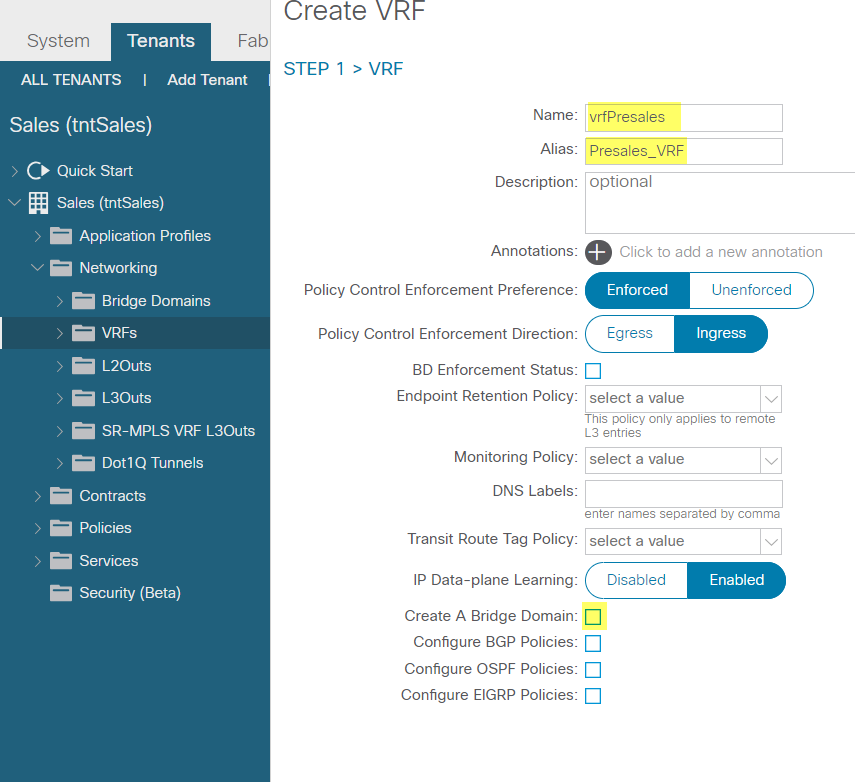
Create VRF
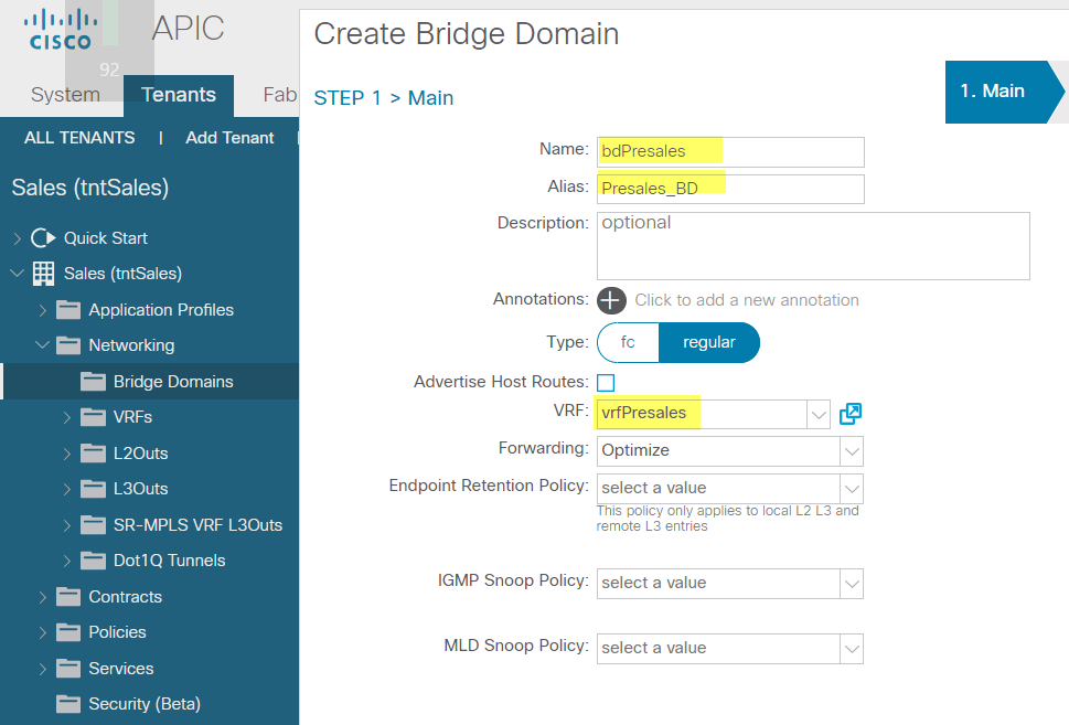
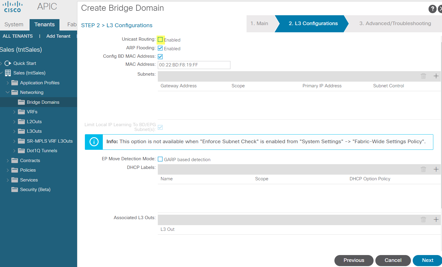
Create bd
Only use L2 communication within the EPG
Next/finish
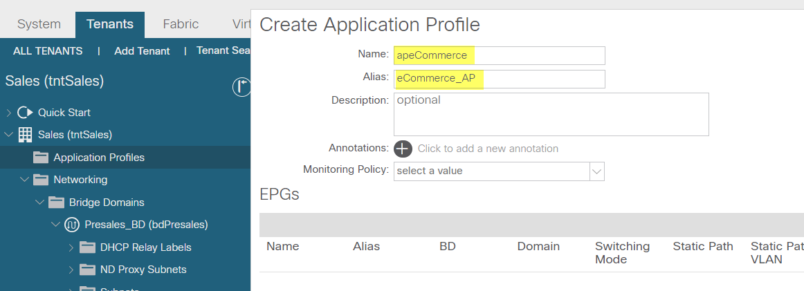
Create Application profile
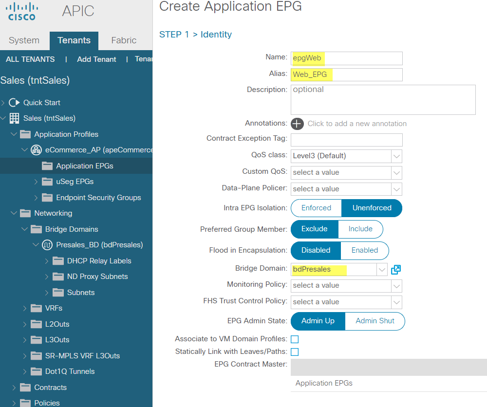
Create EPG
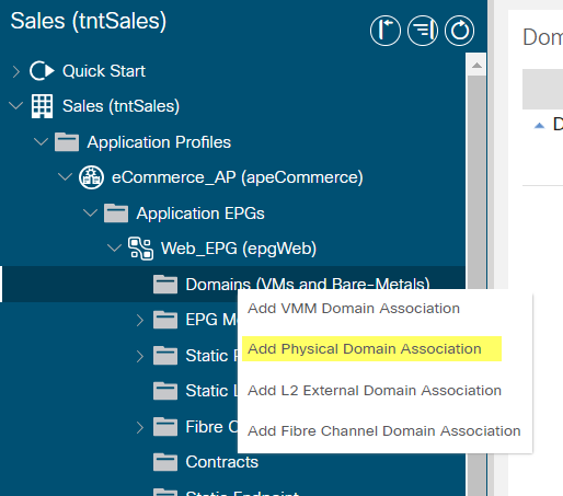
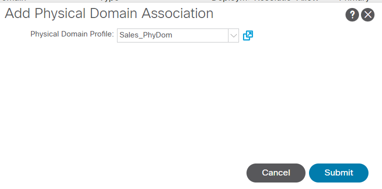
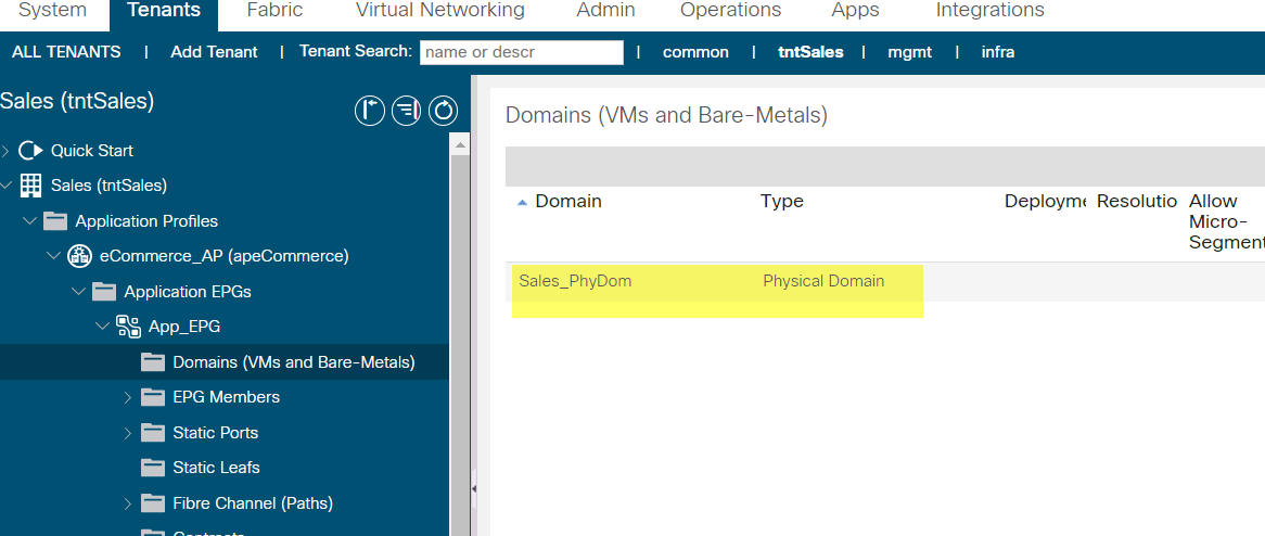
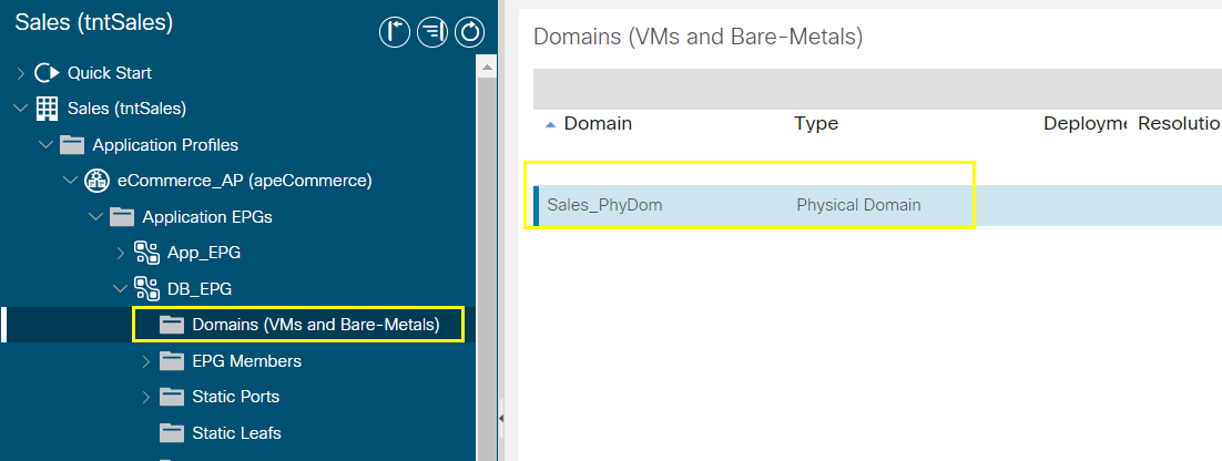
Associate domain to EPG
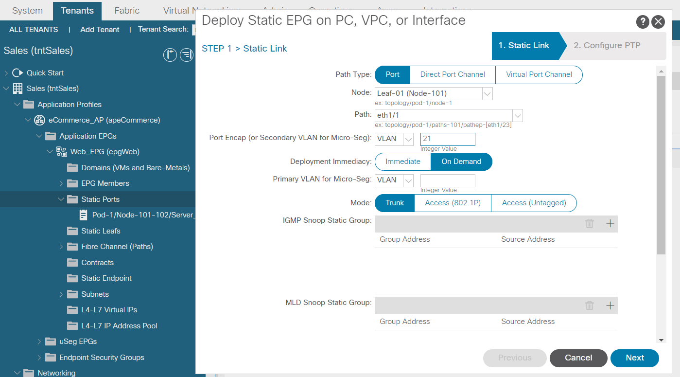
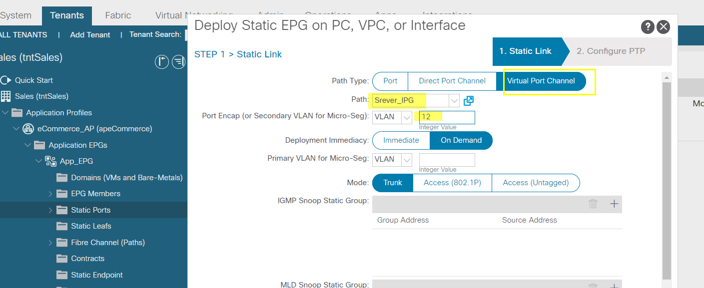
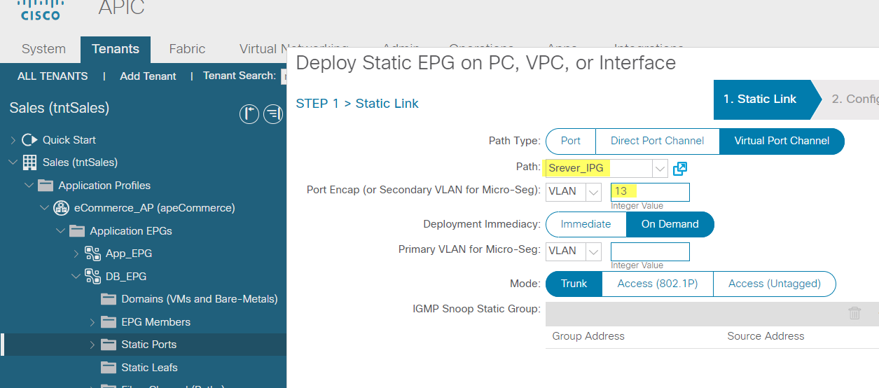
Assign static port vpc
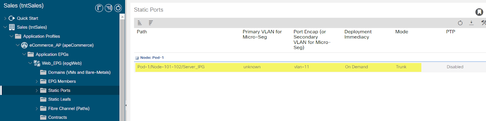
Crate static port
Leaf-a# show vlan extended
Vlan 11 3/13 po4
Vlan 21 e/11
…
--------------------------------------------------------------------------------------------------------------------------------------------------------------------------------------
--------------------------------------------------------------------------------------------------------------------------------------------------------------------------------------
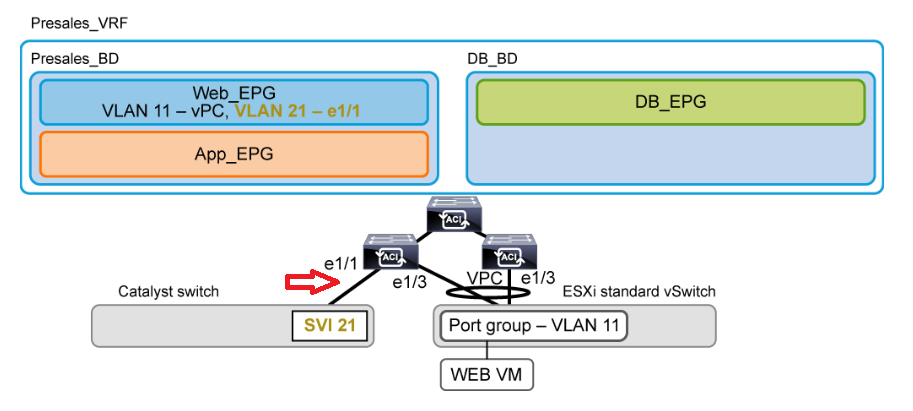
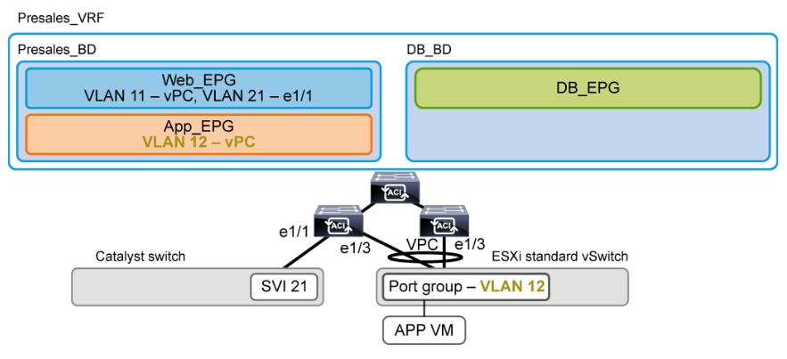
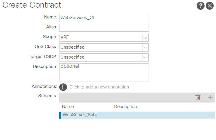
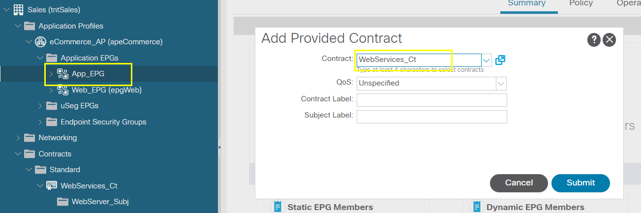
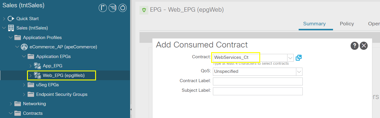
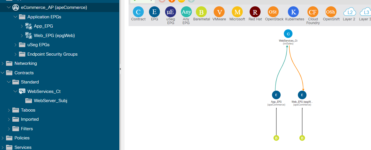
Enable Inter-EPG Layer2 Connectivity
---------------------------------
--------------------------------------------------------------------------------------------------------------------------------------------------------------------------------------
--------------------------------------------------------------------------------------------------------------------------------------------------------------------------------------
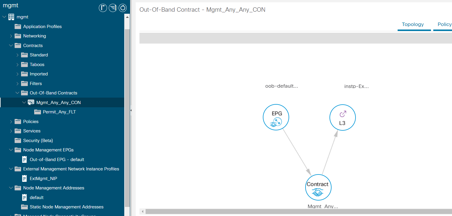
Configuring Out-of-Band Management
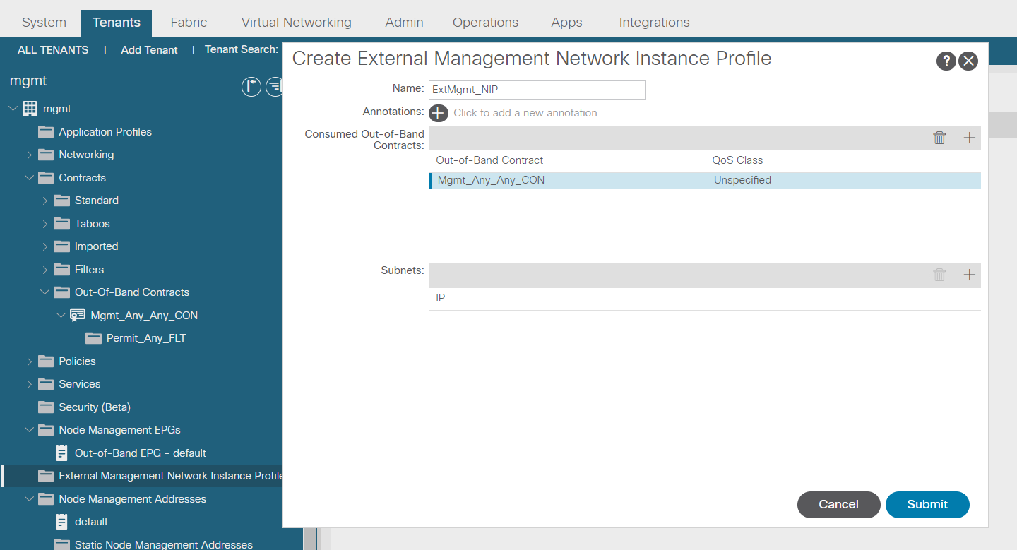
Subnets allow to oob
Verify
--------------------------------------------------------------------------------------------------------------------------------------------------------------------------------------
--------------------------------------------------------------------------------------------------------------------------------------------------------------------------------------
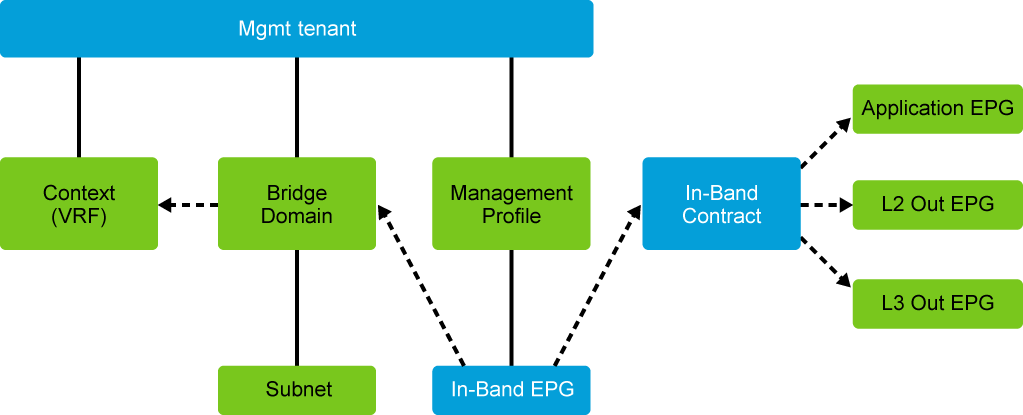
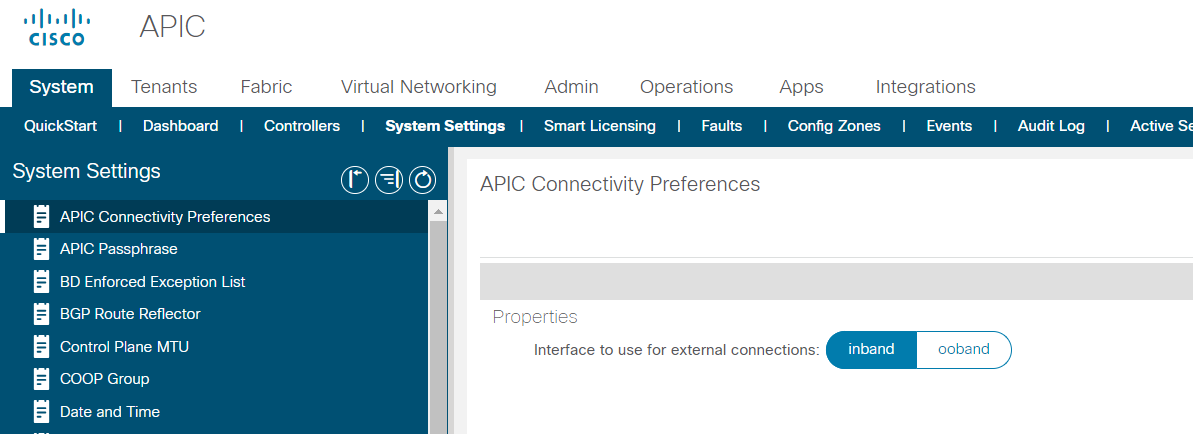
In-Band Management
To access this global toggle in the Cisco APIC GUI, on the menu bar, choose System > System Settings > APIC Connectivity Preferences. As depicted in this figure, you can choose either in-band or OOB.
….
--------------------------------------------------------------------------------------------------------------------------------------------------------------------------------------
--------------------------------------------------------------------------------------------------------------------------------------------------------------------------------------
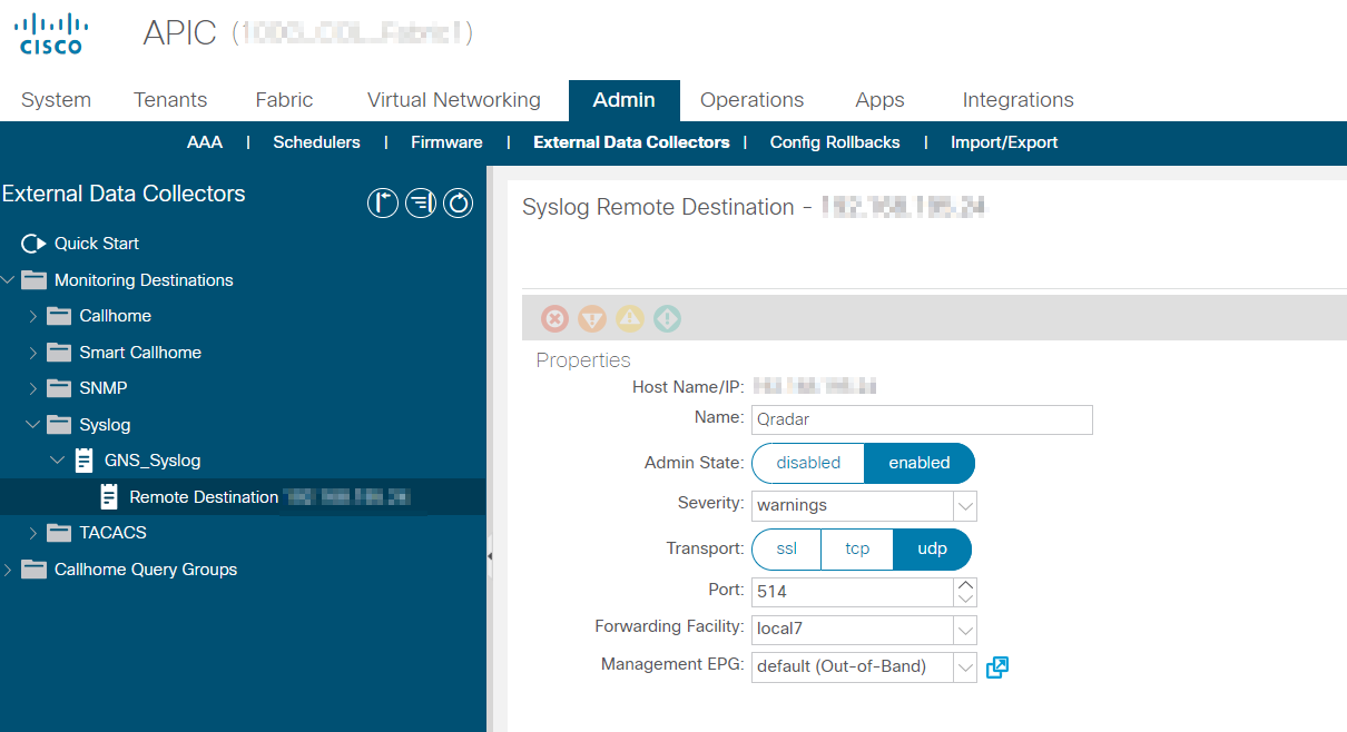
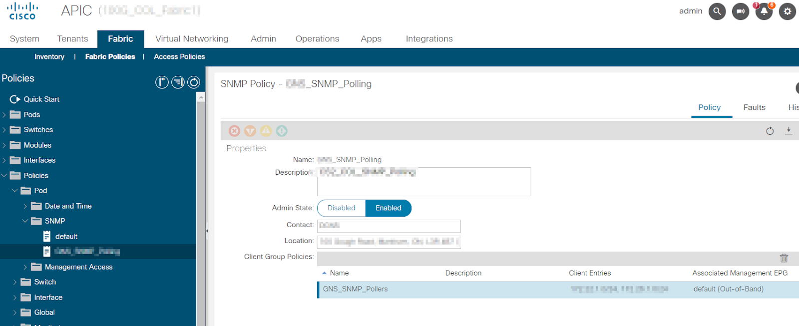
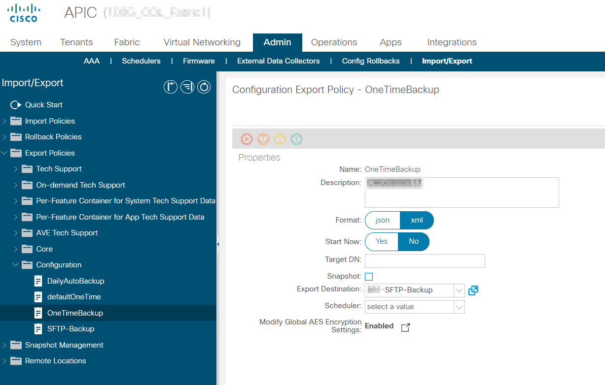
Syslog, SNMP, backup
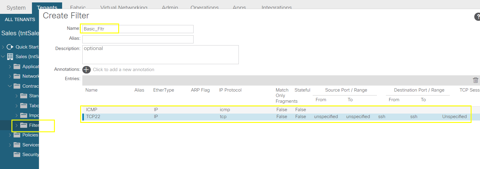
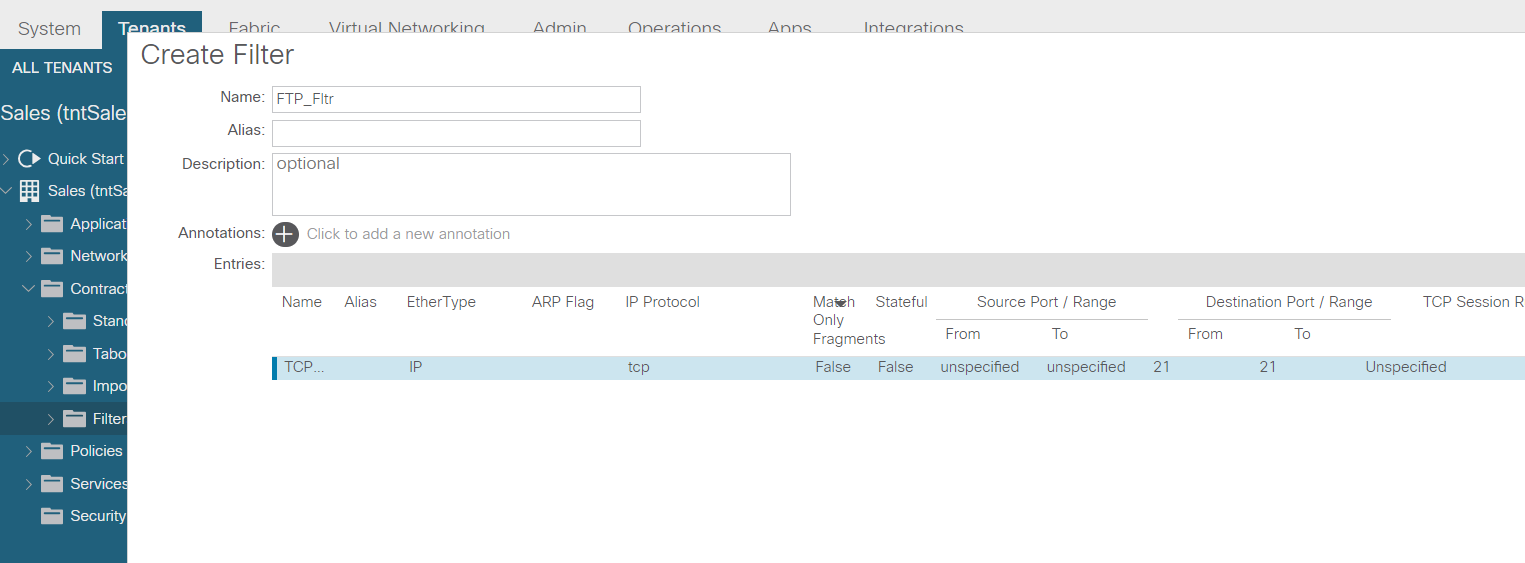
syslog
snmp
backup
--------------------------------------------------------------------------------------------------------------------------------------------------------------------------------------
--------------------------------------------------------------------------------------------------------------------------------------------------------------------------------------
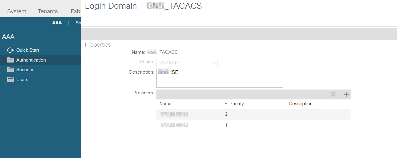
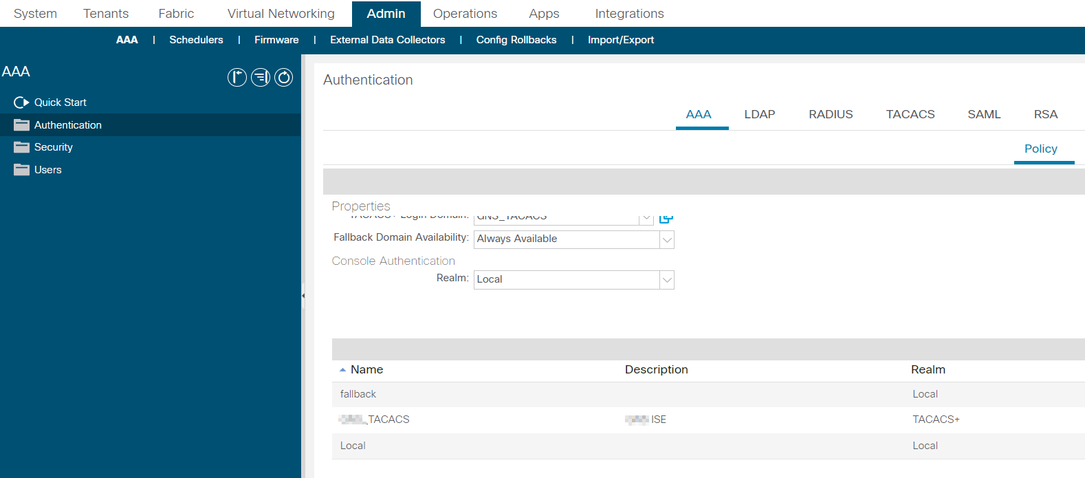
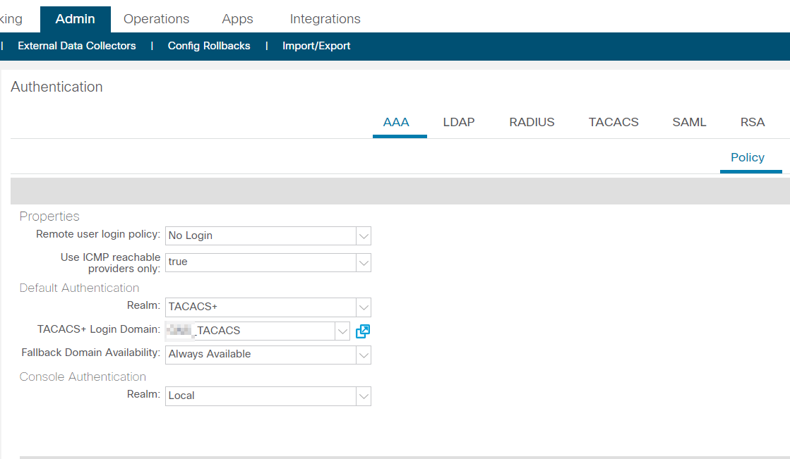
AAA
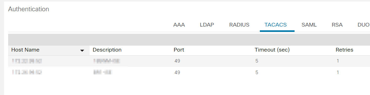
AAA domain
--------------------------------------------------------------------------------------------------------------------------------------------------------------------------------------
--------------------------------------------------------------------------------------------------------------------------------------------------------------------------------------
ACI Upgrade
AAA domain
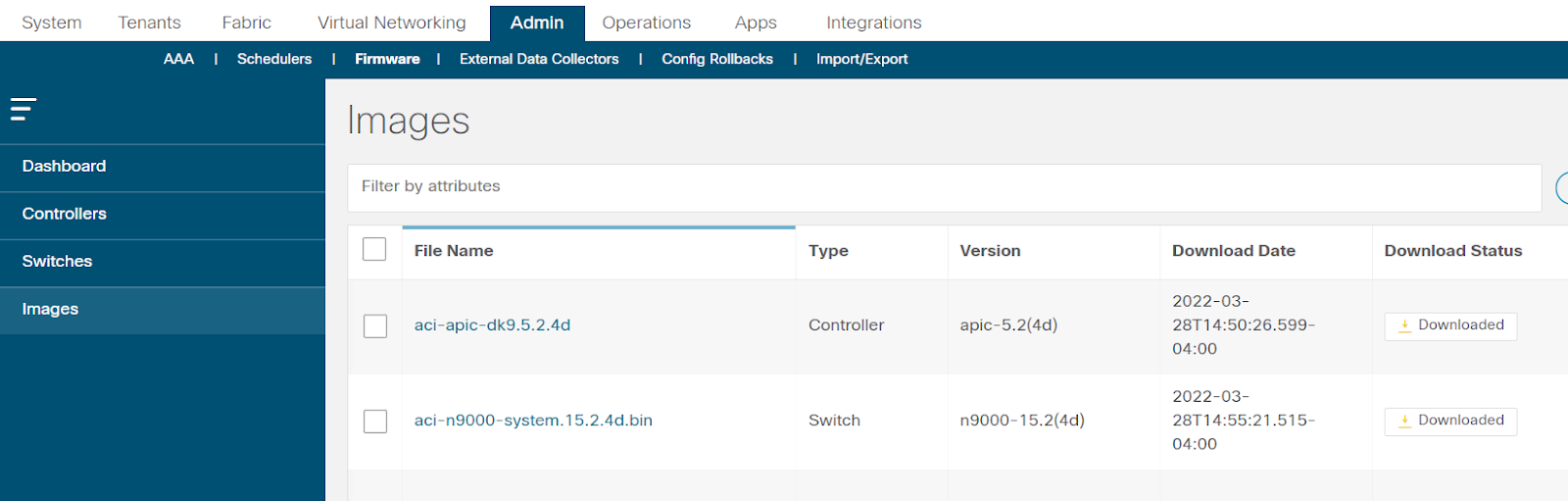
ACI software upgrade
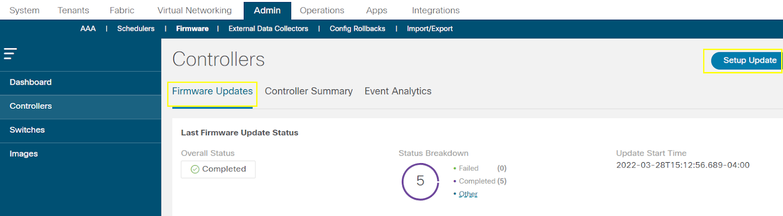
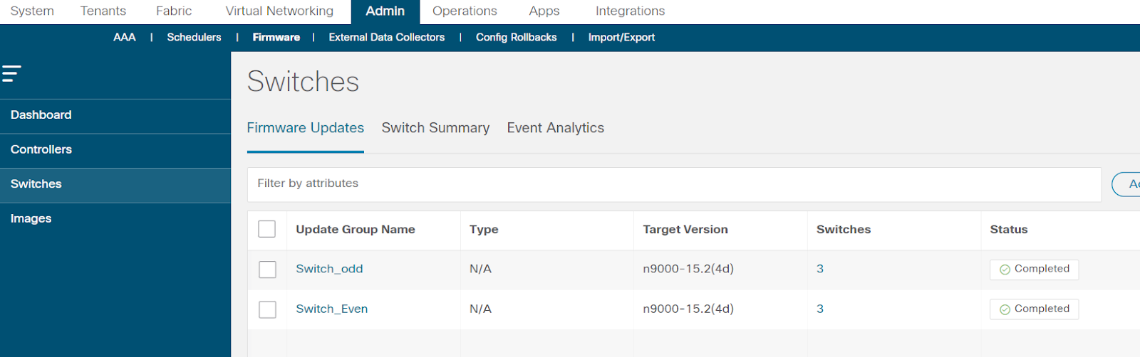
ACI switch software upgrade
--------------------------------------------------------------------------------------------------------------------------------------------------------------------------------------
--------------------------------------------------------------------------------------------------------------------------------------------------------------------------------------
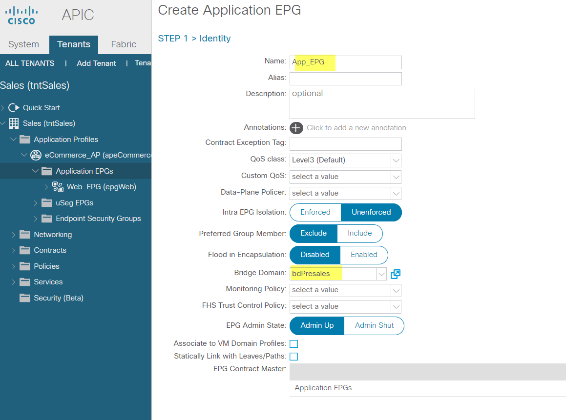
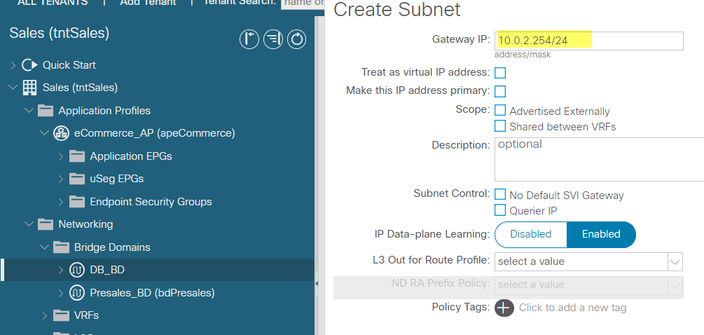
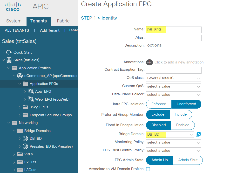
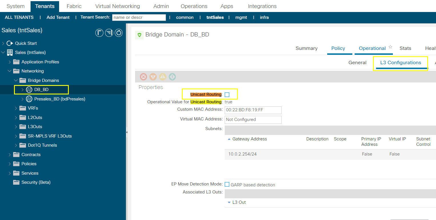
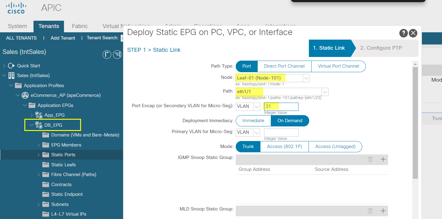
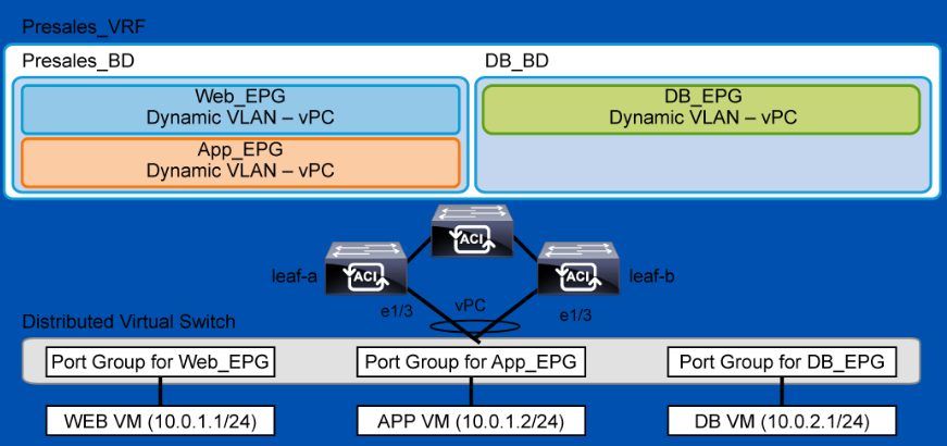
Configure Bridge Domain DB_BD with Subnet and EPG with Static Path Binding
You will extend your scenario by an extra bridge domain (DB_BD) and EPG (DB_EPG). You will configure a static path binding to add a VM to the EPG.


--------------------------------------------------------------------------------------------------------------------------------------------------------------------------------------
--------------------------------------------------------------------------------------------------------------------------------------------------------------------------------------
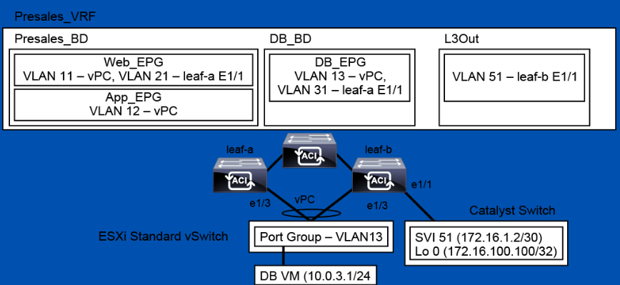
Configure External Layer 2 Connection
The DB_EPG will be extended through Ethernet 1/1, connected to the Cisco Catalyst 3560 Gi1/0/3 interface, using VLAN 31. The subnet of the DB_VM is 10.0.2.0/24. The Cisco Catalyst 3560 has SVI 31 with an IP address in that subnet (10.0.2.254/24), as shown below. Once the EPG is extended and unicast routing is disabled in the DB_BD bridge domain, that SVI will take over the default gateway function for the EPG endpoints.

On the DB_VM, verify that you cannot ping the default gateway or the APP VM.
Configure Static Path Binding for EPG Extension
Examine the IP and MAC address of the switched virtual interface (SVI) for VLAN 31, acting as the new default gateway for the 10.0.2.0/24 that you have brought into the EPG.
--------------------------------------------------------------------------------------------------------------------------------------------------------------------------------------
--------------------------------------------------------------------------------------------------------------------------------------------------------------------------------------
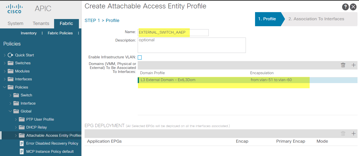
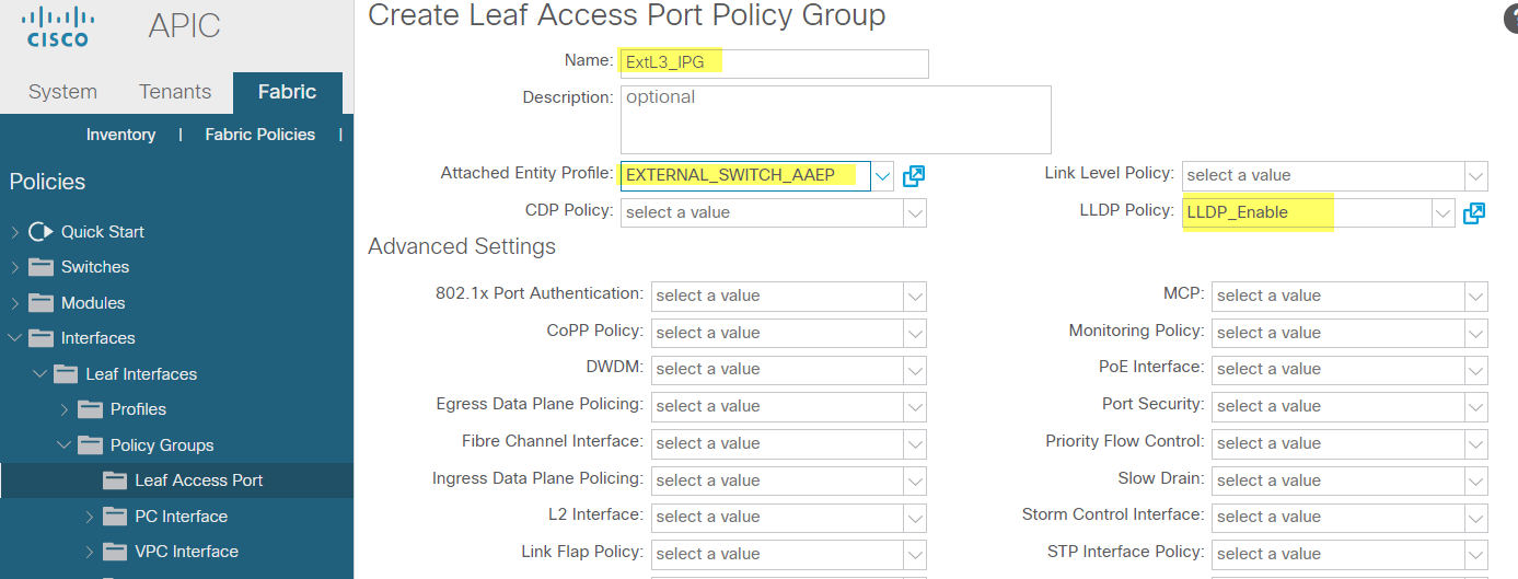
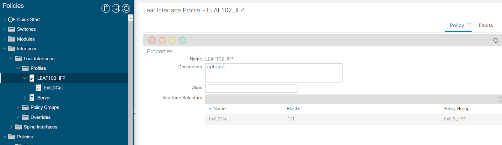
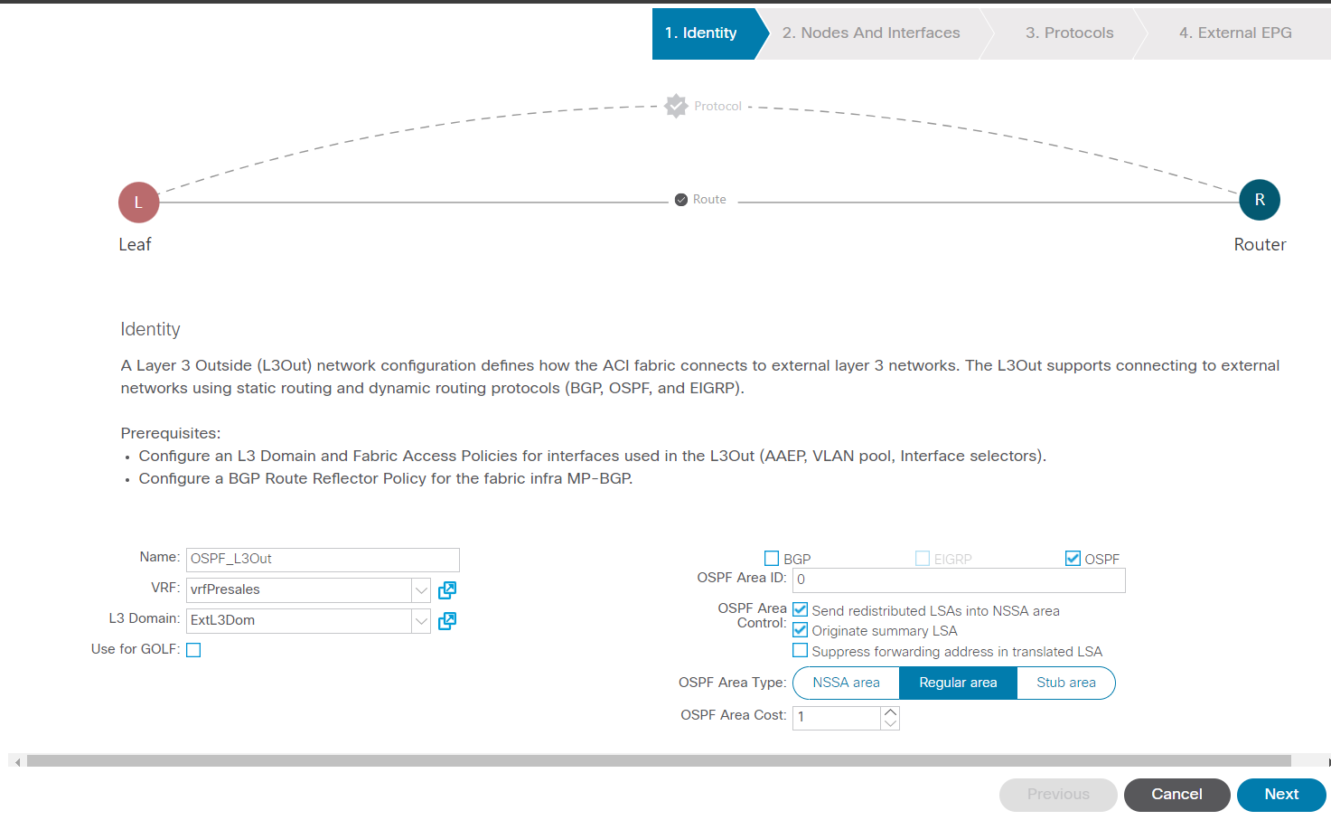
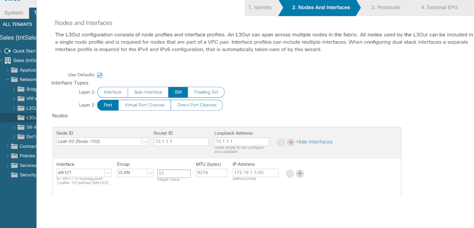
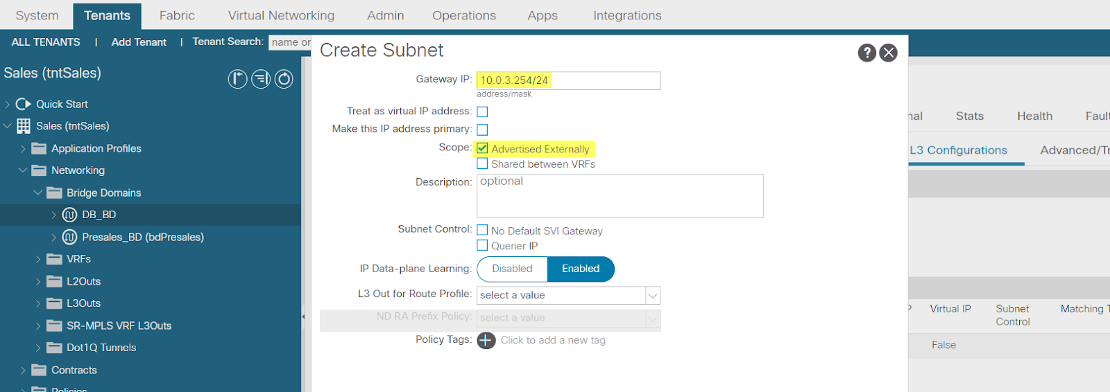
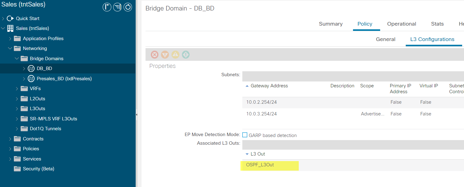
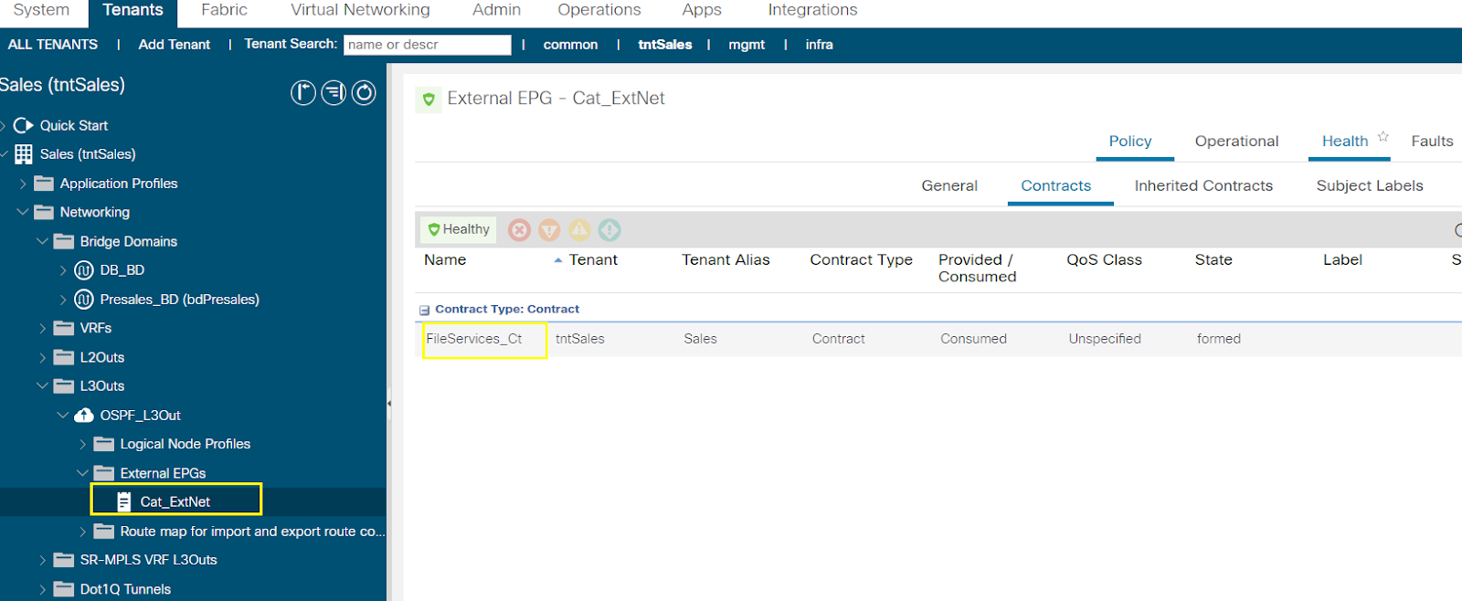
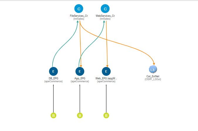
Configure External Layer 3 (L3Out) Connection
In this activity you will deploy OSPF routing between leaf-b and the adjacent Cisco Catalyst switch, and enable communication of the DB_EPG with the external OSPF network, as shown below.
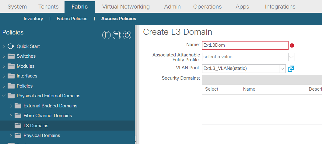
AAEP
Next

Default EPG for all external networks:checked. This is a placeholder for all networks (0.0.0.0/0), to apply the consumed contract to any external network through an external EPG.
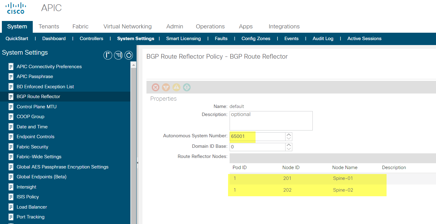
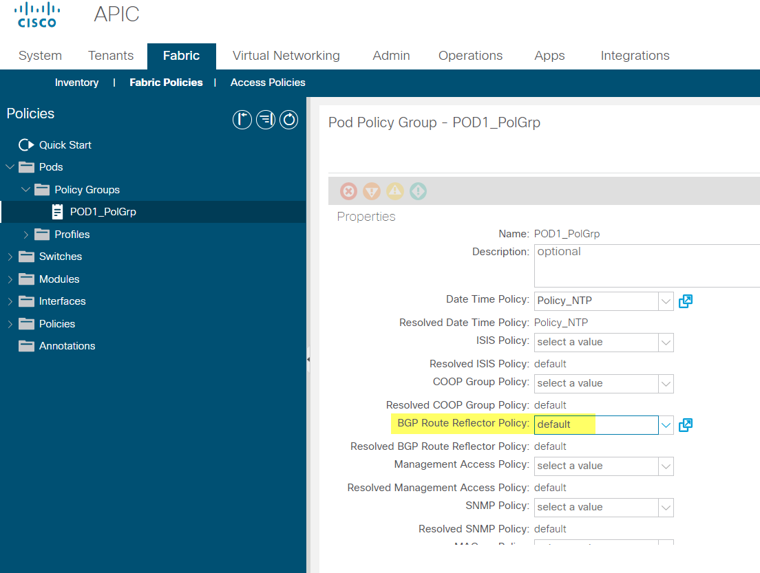
Within the Cisco ACI fabric, Multiprotocol Border Gateway Protocol (MP-BGP) is implemented between leaf and spine switches to propagate external routes within the Cisco ACI fabric. The BGP route reflector technology is deployed to support many leaf switches within a single fabric. All the leaf and spine switches are in a single BGP AS. When a border leaf learns about external routes, it redistributes the external routes of a given VRF to an MP-BGP address family. MP-BGP maintains a separate BGP routing table for each VRF. Within MP-BGP, the border leaf advertises the routes to the spine switch that acts as a BGP route reflector. The routes are then propagated to all the leaves where the VRFs are instantiated.
You will configure a BGP route reflector policy by specifying the BGP AS number and the spine node that should act as the BGP route reflector. Cisco APIC will then automatically enable Internal Border Gateway Protocol (IBGP) peering between leaves and spine (or spines) and configure leaf switches as route reflector clients. Cisco APIC will also automatically generate the required configuration for route redistribution on the border leaves.
--------------------------------------------------------------------------------------------------------------------------------------------------------------------------------------
--------------------------------------------------------------------------------------------------------------------------------------------------------------------------------------
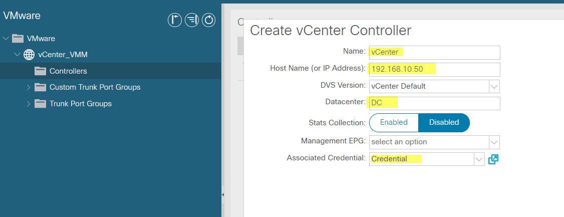
VMware vCenter VDS Integration


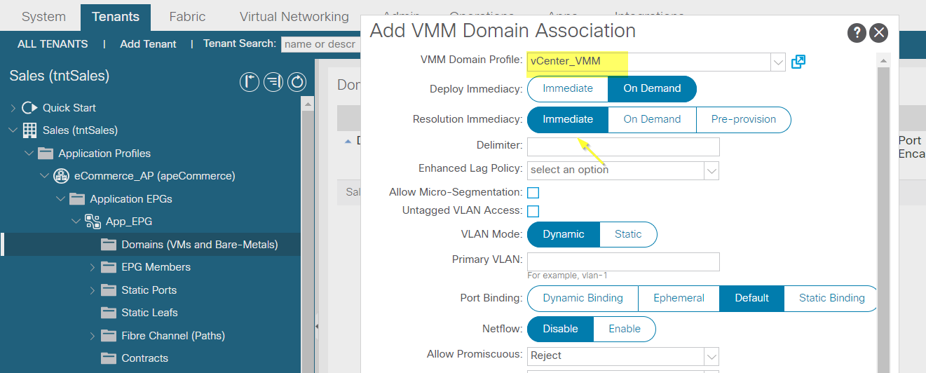

Repeat same for Web_EPG and DB_EPG
No comments:
Post a Comment